Liquid container for liquid-jet head
A liquid container and liquid technology, applied in the direction of instruments, applications, household appliances, etc., can solve the problems of unstable internal negative pressure, ink leakage, and restrictions
- Summary
- Abstract
- Description
- Claims
- Application Information
AI Technical Summary
Problems solved by technology
Method used
Image
Examples
Embodiment 1
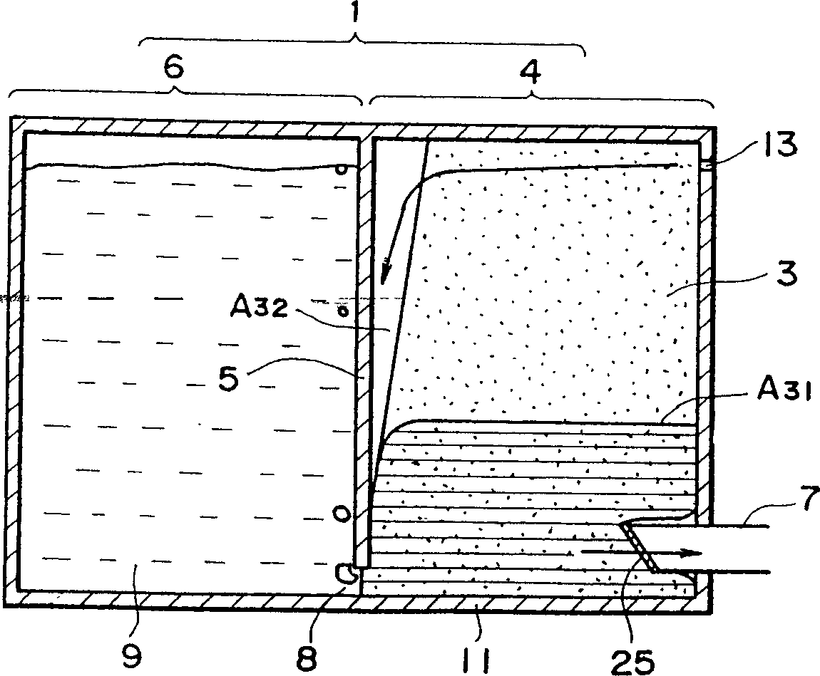
[0110] image 3 represents the first embodiment. The material 3 that creates the vacuum in the ink tank is an ink-absorbing material such as polyurethane foam or the like. When the absorbent material is placed in the vacuum-generating material tank 4, a gap A32 is left in a part of the vacuum-generating material tank to function as a passage for introducing air. This gap extends to the vicinity of the gap 8 between the bottom of the ink tank 11 and the end 8 of the rib 5 . In this way, it communicates with the atmosphere through the vent. When the ink supply from the ink supply portion is started, the ink in the absorbent material 3 is first consumed, so that the internal pressure of the ink supply portion reaches a predetermined value. Then, stably formed in the absorbent material 3 image 3 The ink surface A31 is shown, while a meniscus between the ink and the atmosphere is formed adjacent to the void 8 . The height of the gap 8 is preferably not greater than 1.5 mm, and ...
Embodiment 2
[0142] Figure 5 represents another example device.
[0143] In this embodiment, two ribs 61 are provided on the partition rib 5 of the vacuum-generating material tank 4 . An air introduction passage A51 is formed between these two ribs and the absorbent material 3 . The position of the bottom end A of the rib 61 is higher than the bottom end B of the rib plate 5, so that, as long as a rectangular parallelepiped absorbent material 3 is simply put into the vacuum-generating material tank 4, the gap 8 is covered by the absorbent material 3 . Therefore, the air introduction channel A51 can easily and stably extend to a position very close to the gap 8 . Arrow A52 indicates the air flow direction.
[0144] With this ink tank, the printing process can be effectively performed, and it has been confirmed that Figure 5 The ink surface and meniscus shown in , can be quickly formed due to the ink supply surface caused by the recording work, and the rapid replacement between air an...
Embodiment 3
[0146] Figure 6 A device showing a third embodiment in which the number of ribs 71 is increased to increase the number of air introduction passages. Ribs 71 are provided to separate the vacuum-generating material tanks. According to this embodiment, a plurality of air introduction passages can provide stable airflow from the vent 13 to the vicinity of the gap 8, so, like the first and second embodiments, ink supply can be realized with a small pressure loss, And can stably realize high-speed printing process.
[0147] In this embodiment, even if the passage port 13 is arranged far from the gap 8, air can be smoothly introduced.
PUM
 Abstract
Description
Claims
Application Information
 - R&D
- Intellectual Property
- Life Sciences
- Materials
- Tech Scout
- Unparalleled Data Quality
- Higher Quality Content
- 60% Fewer Hallucinations
Browse by: Latest US Patents, China's latest patents, Technical Efficacy Thesaurus, Application Domain, Technology Topic, Popular Technical Reports.
© 2025 PatSnap. All rights reserved.Legal|Privacy policy|Modern Slavery Act Transparency Statement|Sitemap|About US| Contact US: help@patsnap.com


