Liquid spray unit, method for spraying liquid using it, and chemical

A liquid spraying and liquid technology, which is applied in the direction of liquid spraying device, spraying device, water repellent addition, etc., can solve the problems of difficulty in stable spraying, increase of waste paper mixing ratio, etc.

Inactive Publication Date: 2005-09-14
明答克株式会社
View PDF1 Cites 19 Cited by
  • Summary
  • Abstract
  • Description
  • Claims
  • Application Information

AI Technical Summary

Problems solved by technology

[0019] As mentioned above, due to the advent of paper machines with extremely high speeds, it has become difficult to achieve stable spraying of liquids to moving objects in units employing the above-mentioned technology of shielding surface airflow
[0020] However, at the same time, in consideration of recycling, etc., there is a tendency that the mixing ratio of waste paper, etc. to paper raw materials will increase in the future

Method used


Image

  • Liquid spray unit, method for spraying liquid using it, and chemical
  • Liquid spray unit, method for spraying liquid using it, and chemical
  • Liquid spray unit, method for spraying liquid using it, and chemical

Examples


no. 1 example

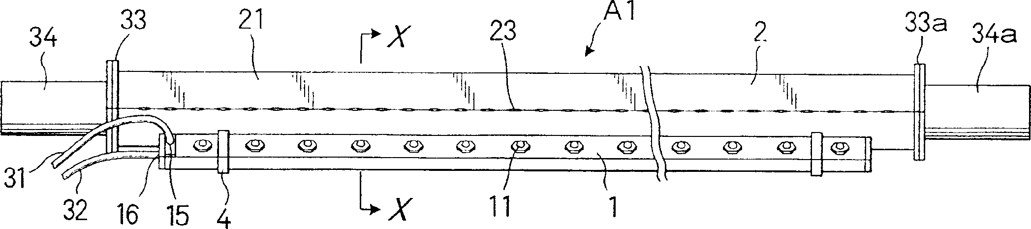
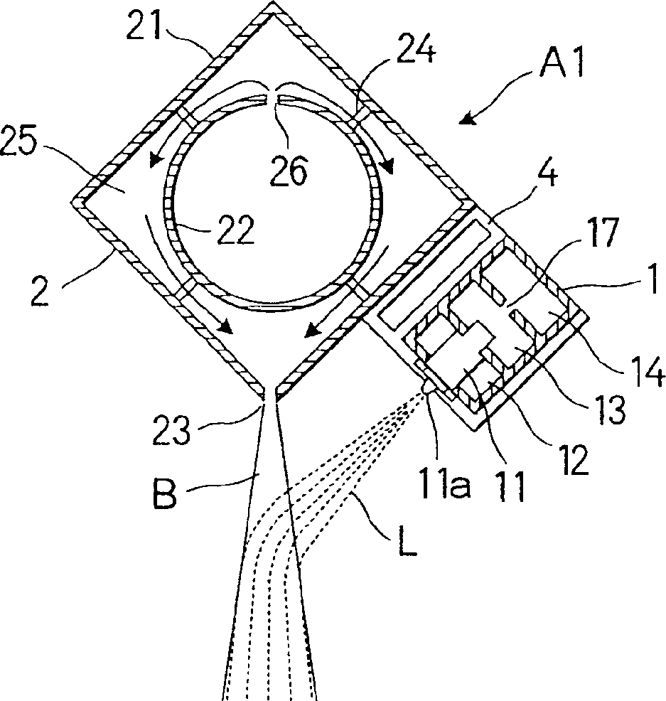
[0065] Figure 1A and 1B is a view showing a structural example of a liquid spraying unit in which a plurality of nozzles are arranged in the width direction of a moving object, in which Figure 1A is a bottom view, Figure 1B It is a sectional view taken along line X-X.

[0066] Such a liquid spray unit A1 is equipped with a spray pipe 1 and a bellows 2 .

[0067] The spray pipe 1 is equipped with a plurality of nozzles 11 arranged in parallel at a fixed distance.

[0068] In this structure example, since the two-flow nozzle is used as the nozzle 11, the spray pipe 1 is equipped with a liquid inlet pipe 12 for feeding liquid to each nozzle 11, an air inlet pipe 13 for feeding compressed air, and a The compressed air pressure is consistent with the pressure regulating pipe 14.

[0069] In this structural example, the spray pipe 1 is integrally formed so that the liquid inlet pipe 12, the air inlet pipe 13, and the pressure regulation pipe 14 formed in a flat rectangular c...

no. 2 example

[0129] As described above, in recent years, the speed of paper machines and the like has become higher, however, there is a tendency that the entire unit becomes more compact and the intervals between components and paper become smaller.

[0130] Thus, there is a state that the liquid spraying unit needs to be made more compact.

[0131] Figure 6 is a cutaway perspective view showing a liquid spraying unit made more compact.

[0132] The liquid spray unit A2 is formed into a compact structure by adopting a structure obtained by installing and fixing the spray pipe 1 to the bellows 2 .

[0133] The spray pipe 1 has the same structure as that of the unit A1 described above, and is designed to adopt the structure used in the unit A1.

[0134] In the same way as unit A1, the bellows 2 is provided with an outer wall 21 and a ventilation duct 22 inside it. The ventilation pipe 22 is fixed to the inner wall of the outer wall 21 through the support piece 24 , and a space 25 is con...

no. 3 example

[0142] Immediately after being conveyed to the drying section of the paper machine, the paper contains relatively large amounts of moisture, and resins, talc, microfibers, etc. tend to transfer from the paper to the drying rolls.

[0143] Therefore, in the case of spraying an antifouling agent containing paraffin or the like, a release agent, etc. on the drying roll, if the spraying is excessive, the paper may be adversely affected on the contrary.

[0144] As mentioned above, small (micro) sprays of liquid are often required when applying liquid to a paper machine or the like.

[0145] FIG. 8 is a perspective view showing a liquid spraying unit A3 suitable for the above-mentioned small amount of liquid spraying.

[0146] The liquid spray unit A3 is configured to spray the liquid while the head 5 including the spray pipe 1 reciprocates in the width direction of the moving object, and to spray and apply the liquid to the moving object.

[0147] First, the head 5 of the liquid ...


PUM


Abstract

A liquid spray unit which can impart liquid (treating liquid, medicine, or the like) surely to a traveling body even in a high speed paper making machine. The liquid spray unit for spraying liquid to a traveling body comprises a spray tube provided with a nozzle for spraying liquid, and an air box provided with an opening for jetting an air flow, wherein the spray tube and the air box are arranged such that the air flow is jetted from the air jet opening toward the liquid sprayed from the spray nozzle and the sprayed liquid can be blown to the traveling body after being accelerated by the air flow. The liquid can be sprayed more effectively to the traveling body by making compact the unit depending on the quantity of liquid being imparted or the inner space of a paper making machine, or the like, or by employing a unit of a type of reciprocating a single nozzle.

Description

technical field [0001] The present invention relates to a liquid spraying unit applied to objects running at high speed, and more particularly to a liquid spraying application unit for firmly applying liquid to various rolls (such as Drying rolls, squeeze rolls, etc.) and on components such as canvas, wire, etc. Background technique [0002] Traditionally, liquids such as paper strength enhancers, interlayer binders, etc., are applied to the paper moving in the paper machine in order to increase the strength of the paper, make multi-ply paperboard, and the like. [0003] Furthermore, in order to prevent the migration of impurities caused by the pulp stock from the paper and to improve the release of the paper, chemicals such as antifouling agents, film release agents, etc. are applied to the components of the paper machine such as wires, felts, drying rolls, canvases, etc. . [0004] Specifically, in recent years, recycling of waste paper and the like has become common, an...

Claims


Application Information

Patent Timeline
Patent Type & Authority Applications(China)
IPC IPC(8): B05B7/08B05B7/24D21F1/34D21G7/00D21H21/02D21H21/16D21H21/18D21H21/22D21H23/50
CPCD21G7/00B05B7/08B05B7/0807B05B7/0861B05B7/0884D21F1/34D21H21/02D21H21/16D21H21/18D21H21/22D21H23/50B05B7/02
Inventor 关谷宏
Owner 明答克株式会社
Why Eureka
Try Eureka