Die head coating, coating device, and method of manufacturing die head for coating

A coating and die technology, which is applied to devices and coatings that apply liquid to the surface, can solve problems such as the inability to achieve the consistency of coating thickness, and achieve cost reduction, inhibition of thickness variation, and inhibition of local variation. Effect

Inactive Publication Date: 2005-09-14
DAI NIPPON PRINTING CO LTD
View PDF1 Cites 4 Cited by
  • Summary
  • Abstract
  • Description
  • Claims
  • Application Information

AI Technical Summary

Problems solved by technology

[0004] However, known coating methods of this type do not achieve the desired thickness uniformity of the coating due to the presence of bands lying in the direction of substrate movement and steps positioned transversely with respect to the direction of substrate movement

Method used


Image

  • Die head coating, coating device, and method of manufacturing die head for coating
  • Die head coating, coating device, and method of manufacturing die head for coating
  • Die head coating, coating device, and method of manufacturing die head for coating

Examples


example

[0079] Next, embodiments of the present invention will be described.

[0080] (1) coating die head: coating die head 12;

[0081] The material of coating die head 12 main body: stainless steel;

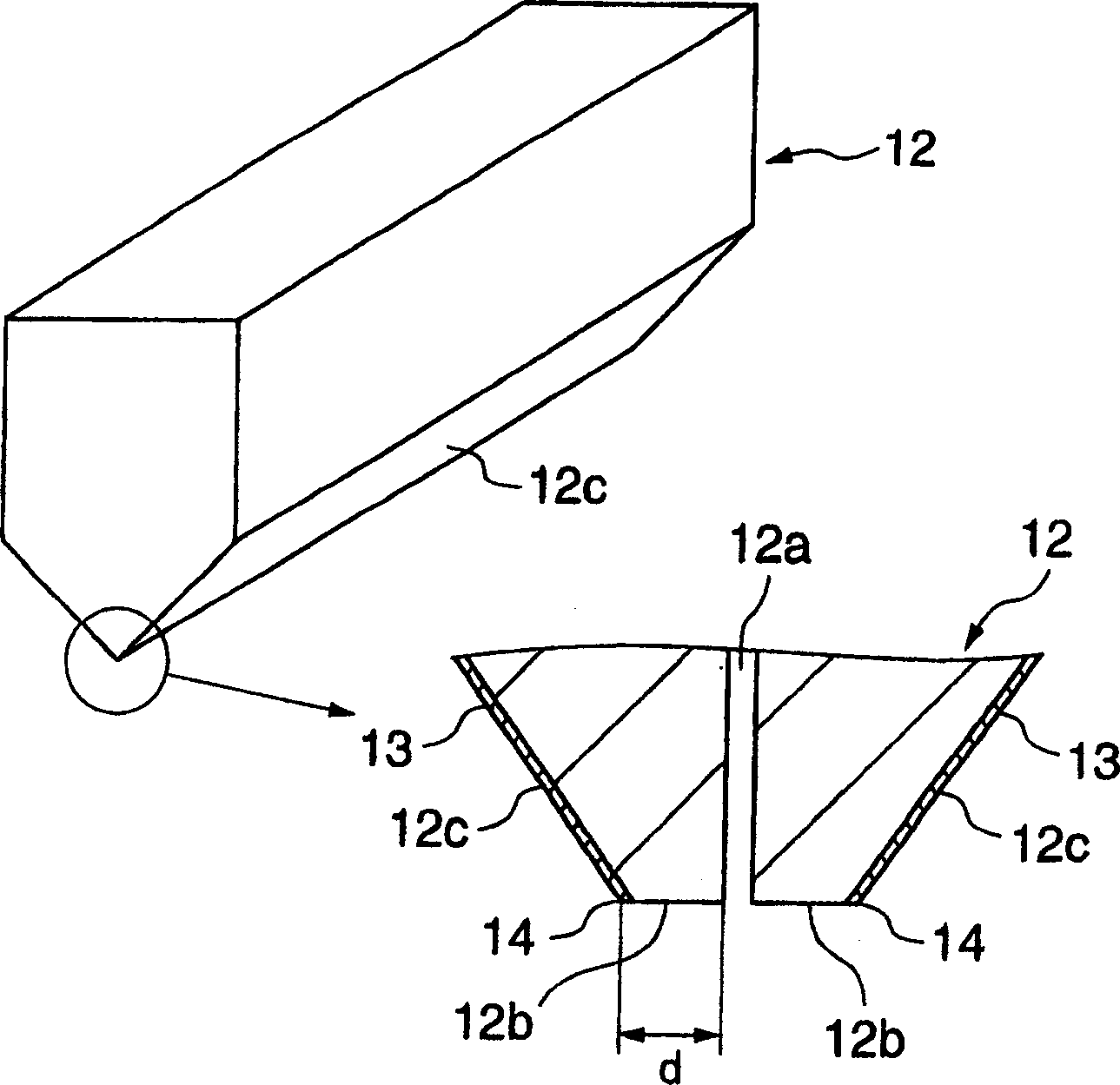
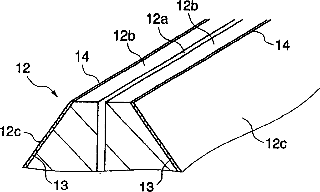
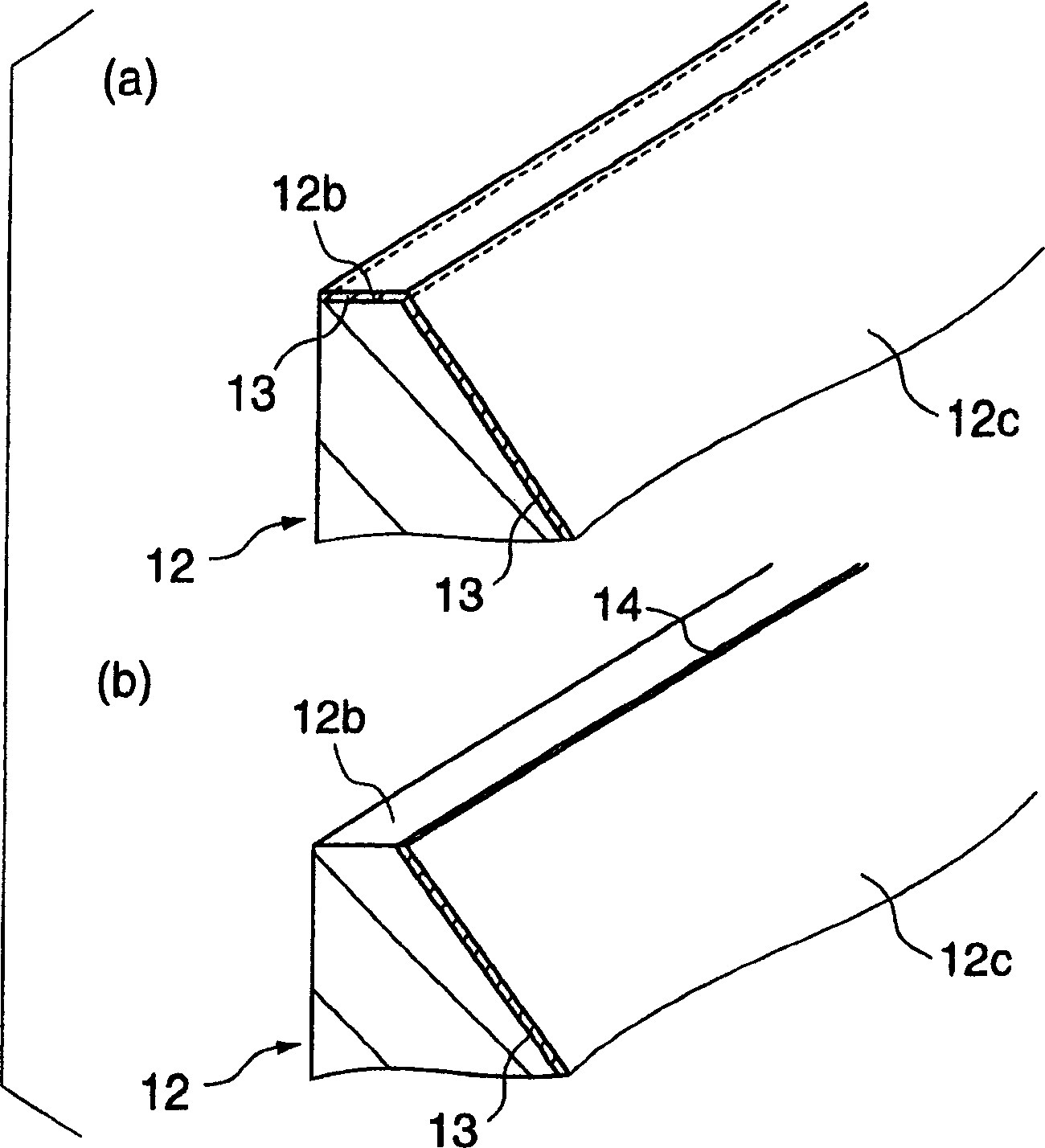
[0082] Flange surface 12b: width: 500 μm;

[0083] Surface: the same material as the main body (stainless steel);

[0084] Surface roughness Rmax: 0.4μm;

[0085] Contact angle relative to the coating liquid: about 7 degrees;

[0086] Side surface 12c: surface: electroless plating of nickel;

[0087] Surface roughness Rmax: 0.4μm;

[0088] Contact angle relative to the coating liquid: about 15 degrees;

[0089] Straightness of the boundary line between the flange surface 12b and the side surface 12c: less than or equal to 5 μm / m;

[0090] (2) Coating liquid

[0091] Color resists on solvent systems;

[0092] Viscosity: 5cP;

[0093] Surface tension: 25dyne / cm;

[0094] (3) Coating conditions

[0095] Such as Figure 4 As shown, with a downwardly oriented coating die 12, a...


PUM

PropertyMeasurementUnit
surface roughnessaaaaaaaaaa

Abstract

During displacement relative to a substrate 1, a coating die head emits coating liquid out of a slot 12a to a surface of the substrate. The coating die head includes a lip 12b having a lip surface 12b and a side having a side surface 12c. A contact angle of the surface 12c with respect to the coating liquid is greater than a contact angle of the surface 12b with respect to the coating liquid. This configuration enhances stabilization of bead of the coating liquid during application process of the coating liquid, preventing stripes and steps from appearing in the coating layer. This coating die head makes it possible to carry out high precision coating required for fabrication of color filters for liquid crystal displays.

Description

technical field [0001] The present invention relates to a coating die, a coating apparatus and a method of making a coating die. Background technique [0002] Typically, the manufacture of color filters for liquid crystal displays involves coating a resist liquid on a substrate, including a glass flake, to provide three layers of red (R), green (G) and blue (B), or to provide protection. surface layer or geometry. For producing the required high precision coatings, spin coating has been used. In spin coating, excess expensive resist material is applied on the substrate surface, and the substrate is rotated at high speed. Spin coating has the problem that the radial velocity of the rotating substrate causes most of the resist material to scatter off the substrate surface, thereby wasting a large amount of applied resist material and causing high production costs. [0003] This problem with spin coating requires an improved method of coating using coating dies such that spi...

Claims


Application Information

Patent Timeline
Patent Type & Authority Applications(China)
IPC IPC(8): B05C5/02
CPCB05C5/0254B05C5/02
Inventor 津田武明吉羽洋青木孝
Owner DAI NIPPON PRINTING CO LTD
Why Eureka
Try Eureka