Method used for working process of printing technique controlling machine

A technology of working process and printing technology, applied to printing machines, general parts of printing machinery, printing, etc., can solve problems such as insufficient processing

Inactive Publication Date: 2005-09-21
HEIDELBERGER DRUCKMASCHINEN AG
View PDF4 Cites 2 Cited by
  • Summary
  • Abstract
  • Description
  • Claims
  • Application Information

AI Technical Summary

Problems solved by technology

The processing of 2D images is insufficient due to the low information content

Method used


Image

  • Method used for working process of printing technique controlling machine
  • Method used for working process of printing technique controlling machine

Examples


Embodiment Construction

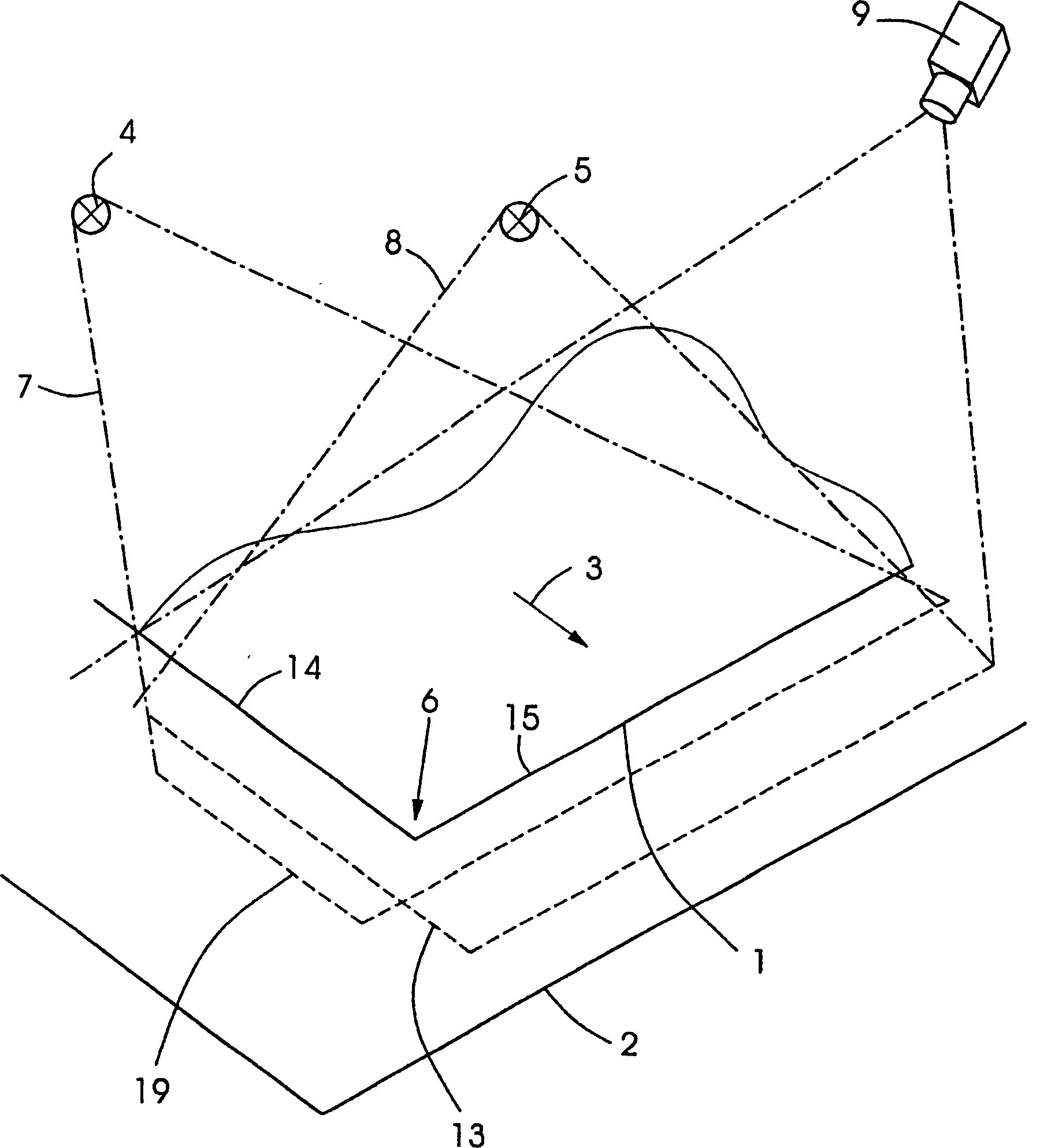
[0025] figure 1 The scene is shown during the transport of a sheet 1 in a printing press. During printing, the sheet 1 is moved by the transport device in the direction 3 past the sheet guide 2 without contact. Arranged above the sheet 1 along the transport path are two light sources 4 , 5 which illuminate a sheet corner 6 and its surroundings. These light sources 4,5 are fixedly arranged at different locations and generate light beams 7,8 of different wavelengths. In order to capture images of the scene, a color camera 9 is permanently arranged at a different location than the light sources 4,5.

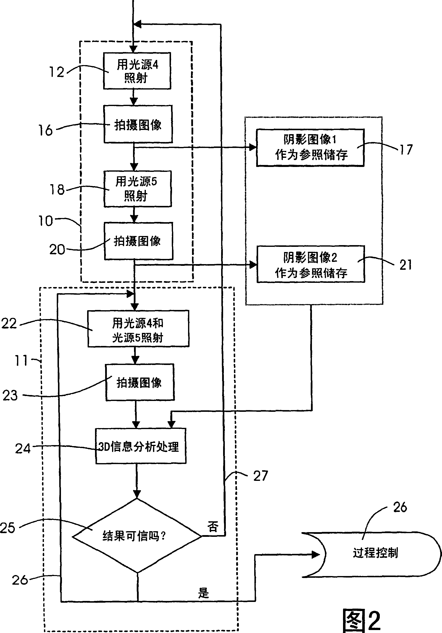
[0026] The implementation of the method is described below with reference to FIG. 2 . These method steps are subdivided into a study phase 10 and a working phase 11 , which are each framed in dashed lines in FIG. 2 .

[0027] In the learning phase 10 a sheet 1 is placed in a position above the sheet guide 2 for the learning record, which corresponds to a desired position during ...


PUM


Abstract

A method for controlling an operating process of a printing machine uses parameters of 3-D scenes taken with only one camera. A learning phase is performed in which the object in a non-moving state and its surroundings are illuminated from different directions by different fixed-location light sources, one after another. For each illumination scene, image signals reproducing the object and its surroundings are obtained with the image recording device. The image signals are processed and an unambiguous association between object edges and object shadows in relation to a light source in each case are determined and stored. In an operating phase, the moving object and its surroundings are illuminated simultaneously by a plurality of light sources, and, from the data stored in the learning phase and the image signals obtained continuously in the operating phase, the position of the object in space is determined.

Description

technical field [0001] The invention relates to a method for controlling the working process of a machine in printing technology, in which method position signals of a moving object are obtained with an image-capturing device, in which method these position signals are processed as desired affect the work process. [0002] The invention enables the automation of paper processing machines, in which the determined state parameters, which are present as 3D scenes, are detected using cameras and image processing devices. The detection of status parameters can be carried out through the vision of the machine operator. Here, the human visual system aids this detection with its spatial perception capabilities, in particular through stereoscopic viewing. The machine operator can successively assume different positions with his head in order to obtain a comprehensive 3D impression. Background technique [0003] From DE 43 21 179 A1 it is known to use a camera for monitoring the pa...

Claims


Application Information

Patent Timeline
Patent Type & Authority Applications(China)
IPC IPC(8): B41F33/14B41F33/00B65H43/08G03B15/00G03B15/02G03B35/02H04N1/40
CPCG06T2207/30108B41F33/00B65H2511/242G06T2207/10152G03B15/00B65H2801/31B65H2553/42B65H2511/20H04N1/40B41F33/14B65H2553/46G06T7/0073G03B35/02G03B15/02B65H2557/63B65H43/08B65H2801/21G06T7/0044G06T2207/10024G06T2207/20081G06T7/74G06T7/586B65H2511/24B65H2220/03B65H2220/02
Inventor 托比亚斯·米勒
Owner HEIDELBERGER DRUCKMASCHINEN AG
Why Eureka
Try Eureka