Feedback sampling control circuit for tube driving systems

A sampling control and drive system technology, applied in nonlinear optics, instruments, optics, etc., can solve the problems of not allowed, sampling lamps, etc.

Inactive Publication Date: 2005-09-21
LOGAH TECH CORP
View PDF0 Cites 2 Cited by
  • Summary
  • Abstract
  • Description
  • Claims
  • Application Information

AI Technical Summary

Problems solved by technology

Although the leakage current I can be eliminated 2 , but this method still cannot sample the actual current I of the lamp in the most accurate way L
Moreover, in the design of many LCD panels, it is not allowed to use this kind of sampling feedback from the low voltage side of the lamp tube.

Method used


Image

  • Feedback sampling control circuit for tube driving systems
  • Feedback sampling control circuit for tube driving systems
  • Feedback sampling control circuit for tube driving systems

Examples


Embodiment Construction

[0032] In order to better understand the technical content of the present invention, several preferred specific examples are given as follows.

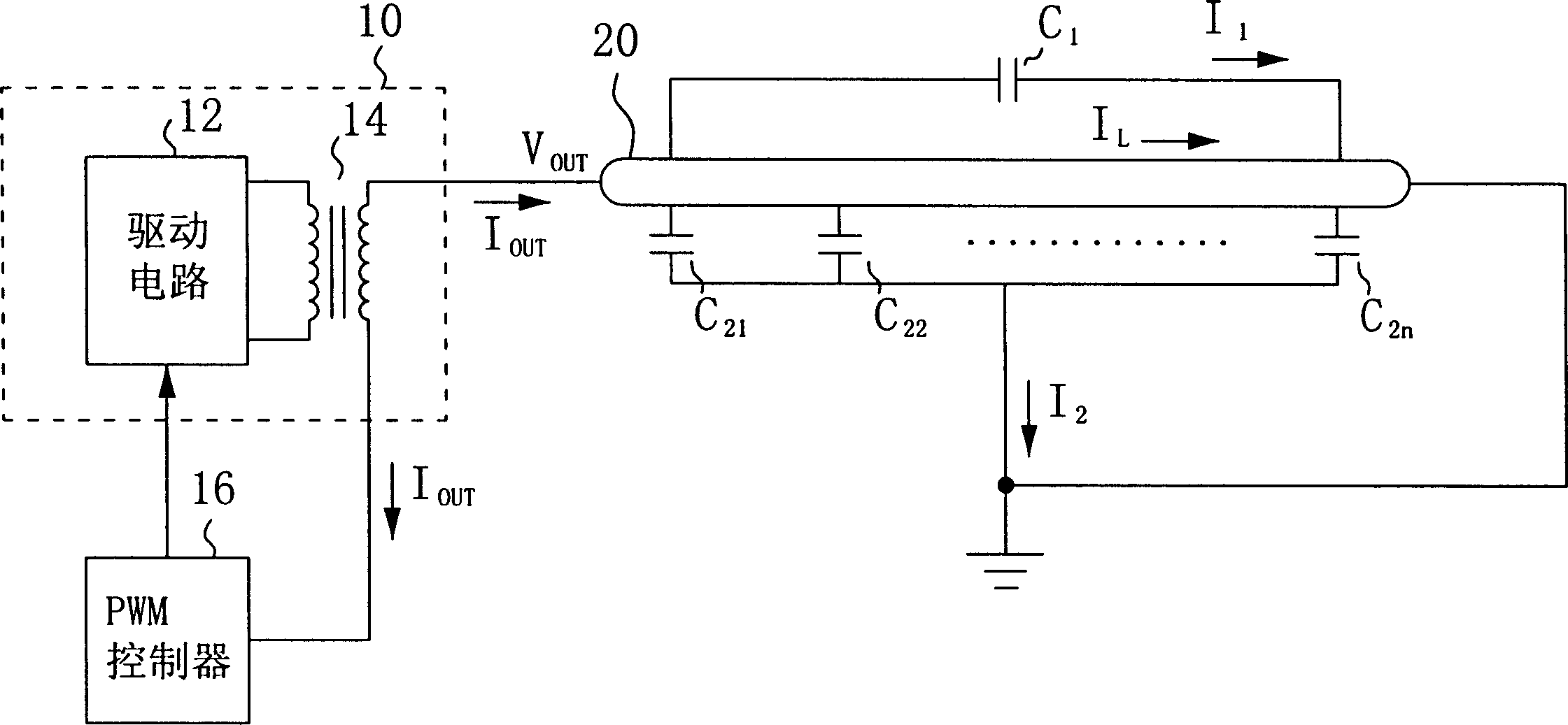
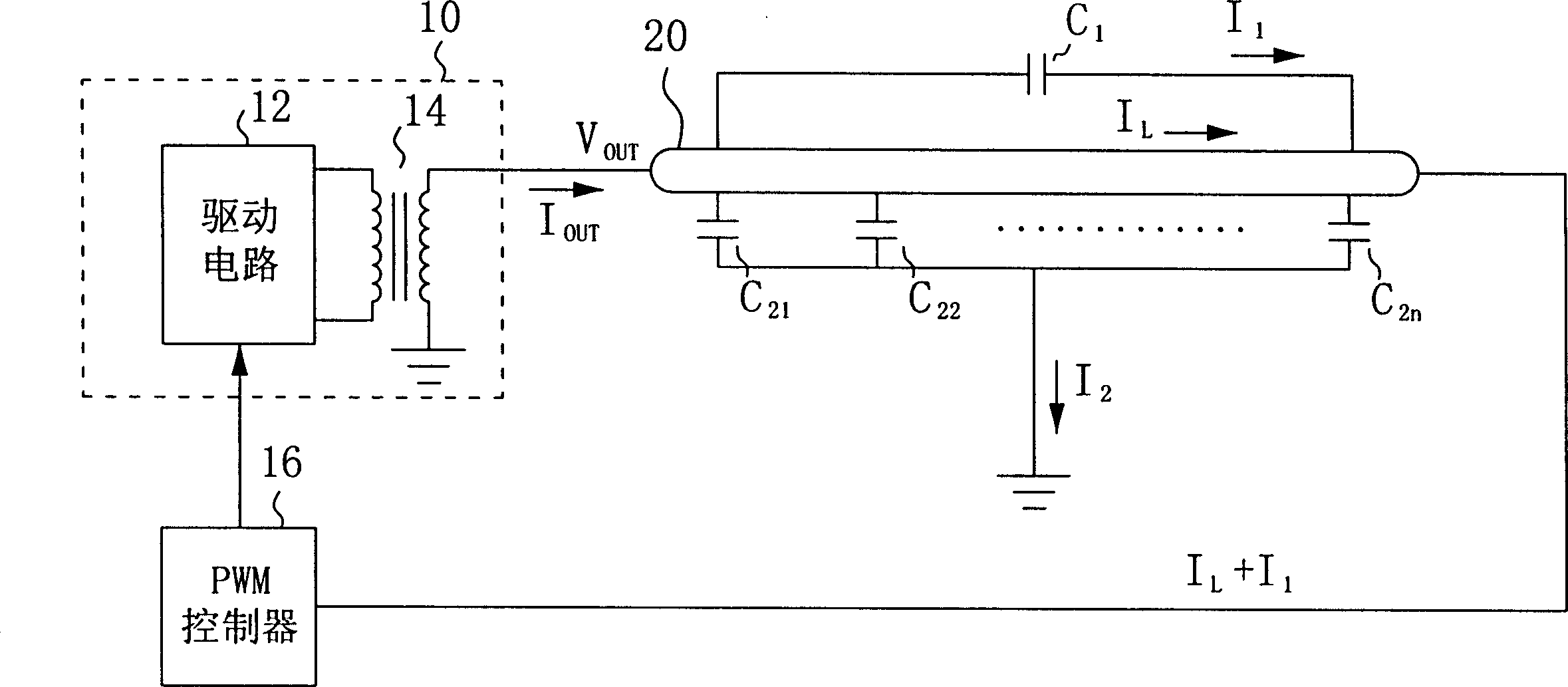
[0033] Figure 4 It is a schematic circuit diagram of a lamp driving system using the feedback sampling control circuit of the first embodiment of the present invention.

[0034] exist Figure 4 In the lamp driving system of the present invention, an inverter 100 mainly includes a driving circuit 120 and a transformer 140 . The driving circuit 120 converts the DC power into an AC signal, and then boosts the voltage through the transformer 140 to generate an AC power supply to a lamp 200 . Here, the output voltage of the converter 100 is V OUT , while the output current is I OUT . A PWM controller 160 can be based on the sampling current I from the secondary side of the transformer 140 OUT And generate a feedback control signal to the driving circuit 120 to adjust the output of the inverter 100 . As previously known in the art, du...


PUM


Abstract

This invention relates to feedback sample control circuit used in one lamp driving system, which comprises one switch device and one current valid value-sampling controller. The switch device is coupled to the lamp driving system feedback route. The current valid value sample controller can control the switch through the voltage or current signals from one end of the lamp and also can control the real sampling valid value in the feedback controller of the lamp driving system to minimize the stray capacity current in the current valid value.

Description

technical field [0001] The present invention relates to a lamp driving system, in particular to an inverter circuit for driving a discharge lamp in a liquid crystal display panel, which has a feedback loop for adjusting the current flowing through the lamp. Background technique [0002] Discharge lamps, especially cold cathode fluorescent lamps (cold cathode fluorescent lamps; CCFL), have the advantages of high efficiency and low cost, so they are widely used in liquid crystal display panels (LCD panels) as light sources for backlight systems . The inverter circuit is used to drive this kind of cold cathode fluorescent lamp, which can supply a very high excitation voltage when the lamp is lit, and reduce the supply voltage to a small operating voltage after the lamp is lit . [0003] figure 1 It is a schematic circuit diagram of a lamp driving system in the known technology. An inverter 10 mainly includes a driving circuit 12 and a transformer 14 . The driving circuit 1...

Claims


Application Information

Patent Timeline
Patent Type & Authority Applications(China)
IPC IPC(8): G02F1/13357G09G3/36
Inventor 许正家潘昱成陈佳園曾荣志吴登和
Owner LOGAH TECH CORP
Why Eureka
Try Eureka