
Exhaust heat recovery system

一种废热回收、热回收的技术,应用在换热器、间接换热器、换热器类型等方向,能够解决尺寸增加、废热回收系统结构复杂等问题,达到发电效率提高的效果

Inactive Publication Date: 2005-09-28
TOYOTA JIDOSHA KK
View PDF1 Cites 19 Cited by
  • Summary
  • Abstract
  • Description
  • Claims
  • Application Information

AI Technical Summary

Problems solved by technology

Therefore, there is a problem that the structure of the waste heat recovery system becomes complicated and its size increases

Method used


Image

  • Exhaust heat recovery system
  • Exhaust heat recovery system
  • Exhaust heat recovery system

Examples


Embodiment Construction

[0032] In the following description, the present invention will be described in more detail based on specific examples.

[0033] Hereinafter, exemplary embodiments of the present invention will be described with reference to the accompanying drawings. The same elements are denoted by the same reference numerals, and their repeated descriptions will be omitted. First, a first embodiment of the present invention will be described.

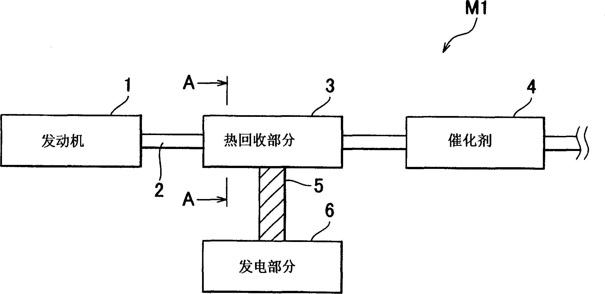
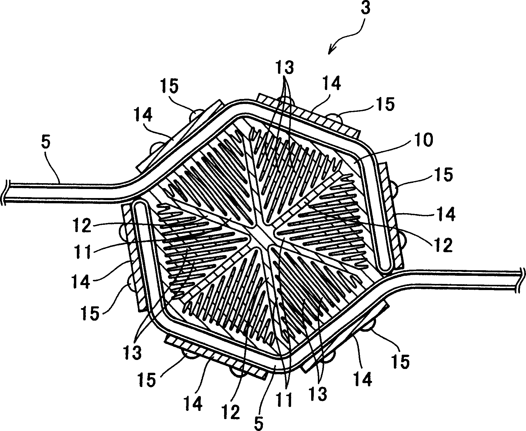
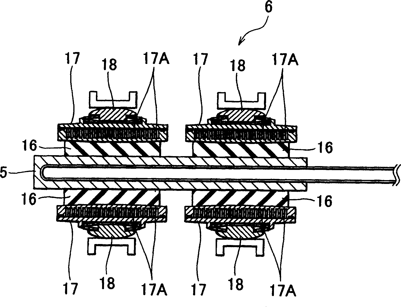
[0034] figure 1 is a schematic structural diagram of the waste heat recovery system according to the first embodiment of the present invention. figure 2 is along figure 1 Sectional view taken along midline A-A. image 3 It is a sectional view of the power generation part.

[0035] Such as figure 1 As shown, the waste heat recovery system M1 according to the first embodiment includes an engine 1, which is an internal combustion engine serving as a heat source, and an exhaust pipe 2 connected to a muffler (not shown). Exhaust gas discharged fro...


PUM


Abstract

The waste heat recovery device M1 is provided with a heat recovery part 3 provided at an exhaust pipe 2, and a power generating part 6 is connected to the heat recovery part 3 through a heat pipe 5. The catalyst 4 is provided downstream in the flow direction of exhaust gas of the heat recovery part 3. The operation start temperature of the heat pipe 5 is set to a higher temperature than the activation temperature of the catalyst 4. Until warming-up of the catalyst 4 is completed, transport of heat by the heat pipe 5 is not performed, but exhaust gas heat is transferred to the catalyst 4 to contribute to early warming-up of the catalyst 4. After warming-up of the catalyst 4 is completed, exhaust gas heat is transported by the heat pipe 5 to a thermoelectric conversion module 16 in the power generating part 6 to contribute to the improvement of power generation efficiency in the thermoelectric conversion module 16.

Description

technical field [0001] The present invention relates to an exhaust heat recovery system used in an automobile such as a hybrid vehicle for recovering thermal energy contained in exhaust gas so as to convert the thermal energy contained in exhaust gas into electric energy. Background technique [0002] Heat energy is contained in exhaust gas or the like discharged from an engine of a car. So if the exhaust is simply emitted, then energy is wasted. For this reason, a technology has been developed that recovers thermal energy contained in exhaust gas using a waste heat recovery system and converts it into electrical energy using a thermoelectric conversion element. The converted electrical energy can be used, for example, to charge a battery. [0003] An example of such a waste heat recovery system is disclosed in Japanese Patent Publication No. 2003-65045. In this waste heat recovery system, a heat pipe is connected to an element of the engine exhaust system, and a thermoel...

Claims


Application Information

Patent Timeline
Patent Type & Authority Applications(China)
IPC IPC(8): F01N3/00F01N3/02F01N3/20F01N3/24F01N5/02
CPCY02T10/16F01N3/2013Y02T10/26F28D15/0275F28D21/0003F28D15/0266H01L35/30F28F1/12F01N5/025Y02T10/12H10N10/13
Inventor 佐佐木俊武
Owner TOYOTA JIDOSHA KK
Learn More