Method and apparatus for forming a sealing member for a display device

一种密封元件、显示装置的技术,应用在密封元件的装置领域,能够解决真空注射法不被广泛采用、增加加工时间、降低生产率等问题

Active Publication Date: 2005-09-28
SAMSUNG DISPLAY CO LTD
View PDF0 Cites 13 Cited by
  • Summary
  • Abstract
  • Description
  • Claims
  • Application Information

AI Technical Summary

Problems solved by technology

[0006] Vacuum injection is not widely used because it involves a complicated process compared to dripping
[0007] However, when the drop method is used, since the drop method coats the strip-shaped sealing member on the substrate in a closed loop structure, it is not possible to continuously form the sealing member on a plurality of LCD devices.
Furthermore, it is difficult to precisely meet closed loop structures whose ends define closed loops and form other closed loops successively
[0008] Therefore, the dropping method increases the processing time required to manufacture a plurality of LCD devices, thereby reducing productivity

Method used


Image

  • Method and apparatus for forming a sealing member for a display device
  • Method and apparatus for forming a sealing member for a display device
  • Method and apparatus for forming a sealing member for a display device

Examples


Embodiment 1

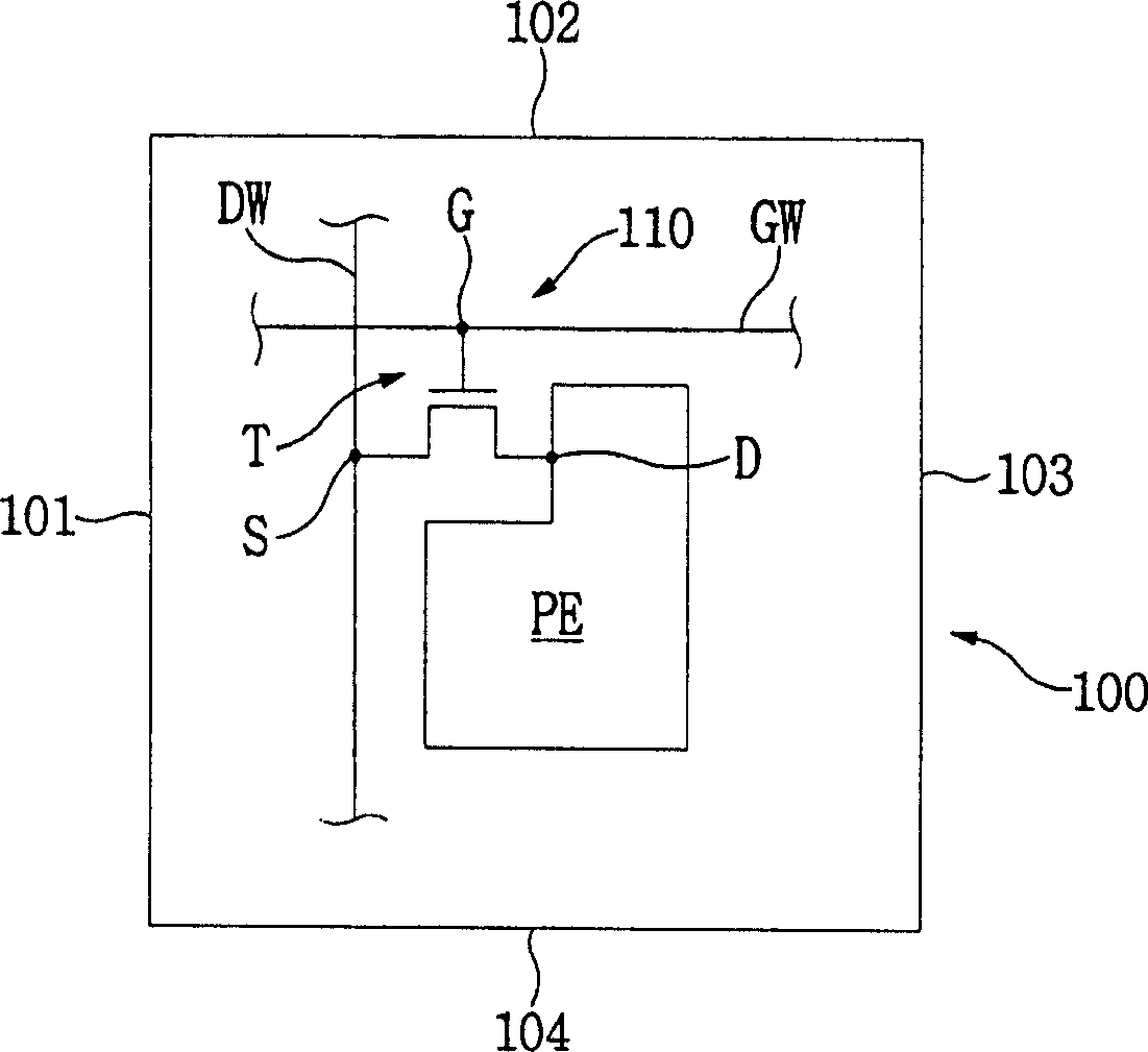
[0053] Figure 1A is a plan view showing a display area sealed by the sealing member forming method according to the first exemplary embodiment of the present invention.

[0054] refer to Figure 1A , the display area 100 is rectangular, and the display area 100 includes a first edge 101 , a second edge 102 , a third edge 103 and a fourth edge 104 . The first and second edges 101 and 102 face the third and fourth edges 103 and 104, respectively.

[0055] Pixels 110 displaying images are formed in the display area 100 . Although not in Figure 1A As shown in , a plurality of pixels may be formed in the display area 100 according to the resolution of a displayed image. For example, a display area with a resolution of 640x480 has 640x480x3 pixels.

[0056] The pixel 110 includes a pixel electrode PE, a thin film transistor T, a gate signal line GW, and a data signal line DW.

[0057] The pixel electrode PE is electrically connected to the drain D of the thin film transistor T....

Embodiment 2

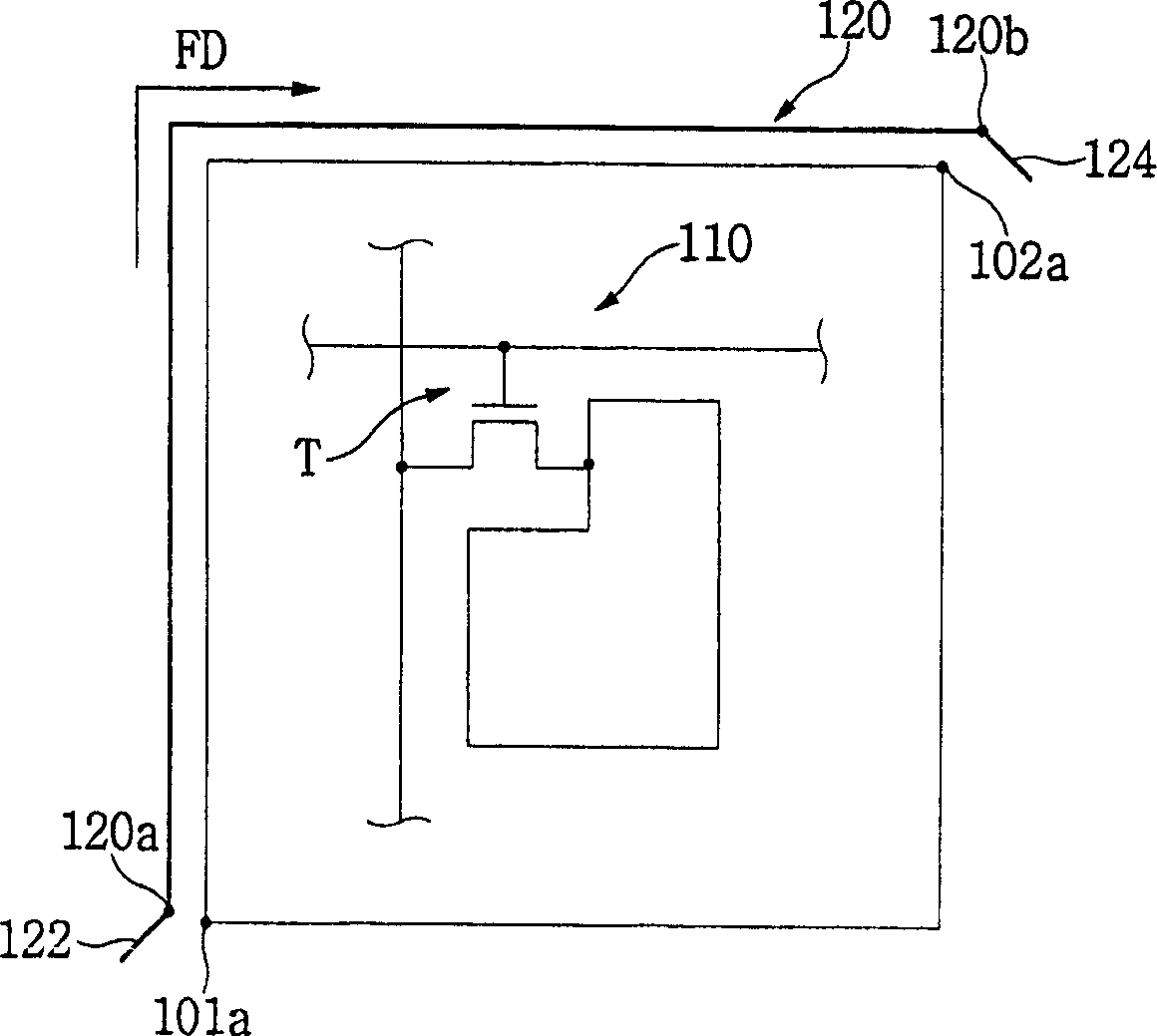
[0070] Figure 2A is a plan view showing a display area sealed by a sealing member forming method according to a second exemplary embodiment of the present invention. Figure 2B with 2C to represent by Figure 2A A plan view of the display area sealed by the first sealing portion and the second sealing portion shown in . In this exemplary embodiment, with Figure 1A The same reference numerals denote the same elements in , and thus detailed descriptions of these same elements are omitted.

[0071] refer to Figure 2B , forming a strip-shaped or linear sealing material along the first direction FD. from Figure 2A The sealing material is formed from the center portion of the first edge 101 to the center portion of the third edge 103 of the display area 100 shown in . As such, the first sealing portion 140 includes the sealing material applied to a portion of the first edge 101 , a portion of the second edge 102 and a portion of the third edge 103 .

[0072] The first sea...

Embodiment 3

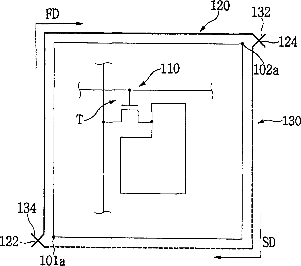
[0081] Figure 3A is a plan view showing a display area sealed by a sealing member forming method according to a third exemplary embodiment of the present invention. Figure 3B with 3C to represent by Figure 3A A plan view of the display area sealed by the first sealing portion and the second sealing portion shown in .

[0082] refer to Figure 3B , forming a strip-shaped or linear sealing material along the first direction FD. from Figure 3A The shown corner portion 101 a where the first edge 101 and the fourth edge 104 meet to the corner portion 103 a where the third edge 103 and the fourth edge 104 meet of the display area 100 form a sealing material. As such, the first sealing portion 160 includes a sealing material applied to the first edge 101 , the second edge 102 and the third edge 103 .

[0083] The first sealing part 160 includes a first connection part 162 and a second connection part 164 , and the first and second connection parts 162 and 164 are formed whe...


PUM


Abstract

A method and apparatus for forming a sealing member includes forming a first sealing part to surround one portion of a display area, the display area including a pixel, and forming a second sealing part to surround a remaining portion of the display area and to intersect ends defining the second sealing part with corresponding ends defining the first sealing part. Thus, a time needed to form the first and second sealing member may be reduced, thereby reducing an entire process time to manufacture the display apparatus. Further, an area needed to form the sealing member may be reduced, thereby enhancing productivity of the display apparatus.

Description

technical field [0001] The invention relates to a method and a device for forming a sealing element of a display device, in particular to a device and a method for forming a sealing element which can increase the number of display panels. Background technique [0002] In order to visually confirm information processed in an information processing device, a display device is often used as an interface. Various display devices such as, for example, cathode ray tube (CRT) display devices, liquid crystal display (LCD) devices, plasma display panels (PDP), organic electroluminescent display (EL) devices, and the like can be used as the interface. [0003] The LCD device displays images using various characteristics, such as twist, spray, band, etc., generated when an electric field is applied to liquid crystals, for example. [0004] The LCD device includes a pair of substrates, a pair of electrodes, a liquid crystal layer and a sealing member. Electrodes are formed on the subs...

Claims


Application Information

Patent Timeline
Patent Type & Authority Applications(China)
IPC IPC(8): G09F9/30G02F1/1339G02F1/1341
CPCG02F2001/13415G02F1/1339G02F1/133351G02F1/13415F26B3/02F26B2200/04B09B3/40
Inventor 李源规金炯杰宋俊昊
Owner SAMSUNG DISPLAY CO LTD
Why Eureka
Try Eureka