Internal combustion engine with cylinder lubricating system

A technology for lubrication systems and internal combustion engines, applied in the direction of pressure lubrication of lubrication pumps, control of lubricant pressure, timing lubrication, etc., can solve problems such as increased consumption of lubricating oil, difficulty in forming, sticking, etc., to avoid lack and prevent lubrication Effect of reduction in oil supply

Inactive Publication Date: 2005-10-05
MITSUBISHI HEAVY IND LTD +1
View PDF1 Cites 26 Cited by
  • Summary
  • Abstract
  • Description
  • Claims
  • Application Information

AI Technical Summary

Problems solved by technology

Moreover, when some of the plurality of lubricators fail, other normally operating lubricators cannot take the place of the failed lubricator, and therefore, the inner surface of the cylinder tends to be worn or damaged due to the deterioration of the state of lubrication. bond
[0005]The above-mentioned problems will occur when using the existing technology, and it is difficult to form a layer of oil film extending in a large range, especially along the axial direction of the inner surface of the cylinder
Therefore, it is difficult to achieve a lubricating performance that can meet the demands of increasing engine output
[0006] Also, in the prior art, it is difficult to control the timing of spraying the lubricating oil to the inner surface of the cylinder, that is, when the lubricating oil is sprayed to the inner surface of the cylinder , it is difficult to control the position of the piston, the piston may appear in a position where it cannot be effectively lubricated, resulting in a tendency that the consumption of lubricating oil will increase, and wear or adhesion will also cause insufficient lubricating oil distribution on the inner surface of the cylinder Occurs at location

Method used


Image

  • Internal combustion engine with cylinder lubricating system
  • Internal combustion engine with cylinder lubricating system
  • Internal combustion engine with cylinder lubricating system

Examples


Embodiment Construction

[0063] Preferred embodiments of the present invention will be described in detail below with reference to the accompanying drawings. However, it should be understood that, unless otherwise stated, the dimensions, materials, corresponding positions, etc. of the components in the embodiments are merely illustrative examples, rather than limiting the scope of the present invention.

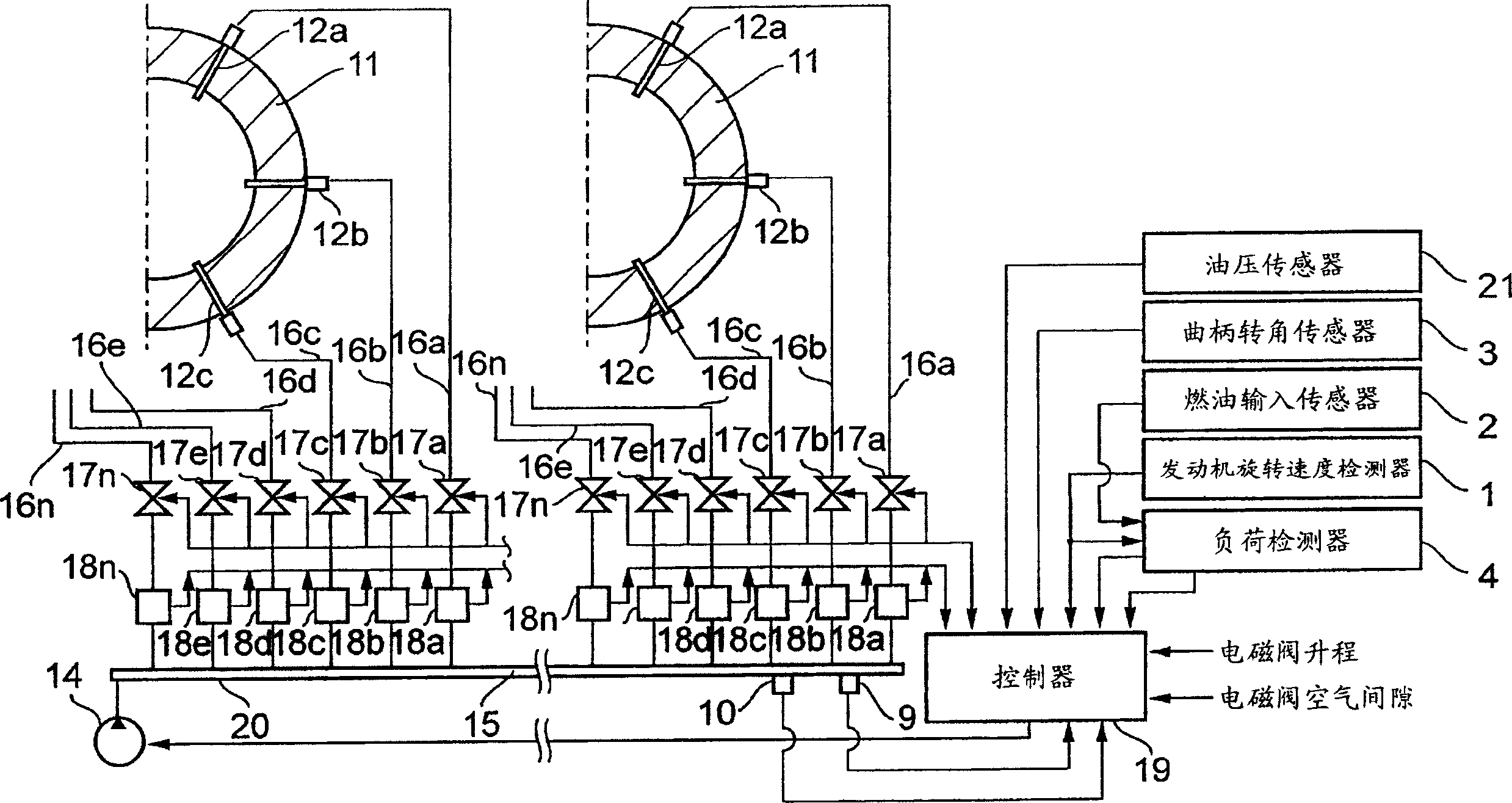
[0064] figure 1 It is the overall connection diagram of the first embodiment of the electronically controlled lubrication system of the present invention.

[0065] see figure 1 , reference numeral 11 is a cylinder liner, and two cylinder liners (cylinders) are shown in the figure. Reference numerals 12 a , 12 b , 12 c . . . , 12 n (omitted) are lubricators for supplying lubricating oil to the inner surfaces of the respective cylinders 11 . A plurality of lubricators 12a, 12b, 12c..., 12n are arranged along the circumference of each cylinder 11, preferably distributed at equal intervals.


PUM


Abstract

An internal combustion engine with a cylinder lubricating system is proposed; with the system it becomes possible to supply lube oil of required amount at required timing to each of lubricators, and normal supply of lube oil is possible even when malfunction occurs in some of the lubricators or magnetic valves, and further the timing and amount of lube oil supply can be adjusted even in engine operation in accordance with varying factors such as properties of lube oil, lube oil pressure, etc., resulting in a reduction of lube oil consumption. Lubricating oil pressure-fed by a lubricating oil pump is accommodated in a common lube oil feeding section, the lubricating oil accumulated in said common lube oil feeding section is supplied to a plurality of lubricators (injectors) through oil passages connecting said common lube oil feeding section to said lubricators and injected to the inner surfaces of cylinders of the engine by said lubricators, a plurality of electromagnetic valves are provided for opening or closing the oil passages and the timing and period of opening of each of the valves are controlled independently so that lube oil is injected from the lubricators to spaces between piston rings once per one reciprocation of piston.

Description

technical field [0001] The present invention relates to an internal combustion engine having a cylinder lubricating system applied to a large marine diesel engine, etc., lubricating oil pressure-supplied by a lubricating oil pump is accommodated in a common lubricating oil supply part, by the system, in the common lubricating oil supply part The lubricating oil is supplied to a plurality of lubricators mounted on the cylinders of the engine so as to be supplied to the inner surfaces of the cylinders. Background technique [0002] A mechanical cylinder lubrication system has been widely used in large marine diesel engines, wherein, as disclosed in Patent Document 1 (Japanese Laid-Open Utility Model Application No. 59-175619), a plurality of lubricators are arranged along the cylinder's Lubricating oil supplied under pressure by a plunger type oil pump driven by rotation is supplied to the inner surface of the cylinder by means of the lubricator. [0003] In this lubricating ...

Claims


Application Information

Patent Timeline
Patent Type & Authority Applications(China)
IPC IPC(8): F01M1/16F01M1/02F01M1/06F01M1/08F01M1/14F01M9/00F02D45/00
CPCF01M1/08F01M1/14F01M2001/083F01M2011/022F01M1/06F01M1/16F02F1/20
Inventor 村田聪吉原定男山本哲也和泉基辉园田隆
Owner MITSUBISHI HEAVY IND LTD
Why Eureka
Try Eureka