Converter circuit and control method for same

A converter circuit and control device technology, applied in control/regulation systems, output power conversion devices, instruments, etc., to achieve the effect of reducing switching losses

Inactive Publication Date: 2005-10-12
KONINKLIJKE PHILIPS ELECTRONICS NV
View PDF2 Cites 44 Cited by
  • Summary
  • Abstract
  • Description
  • Claims
  • Application Information

AI Technical Summary

Problems solved by technology

This problem also accompanies other converter layouts

Method used


Image

  • Converter circuit and control method for same
  • Converter circuit and control method for same
  • Converter circuit and control method for same

Examples


Embodiment Construction

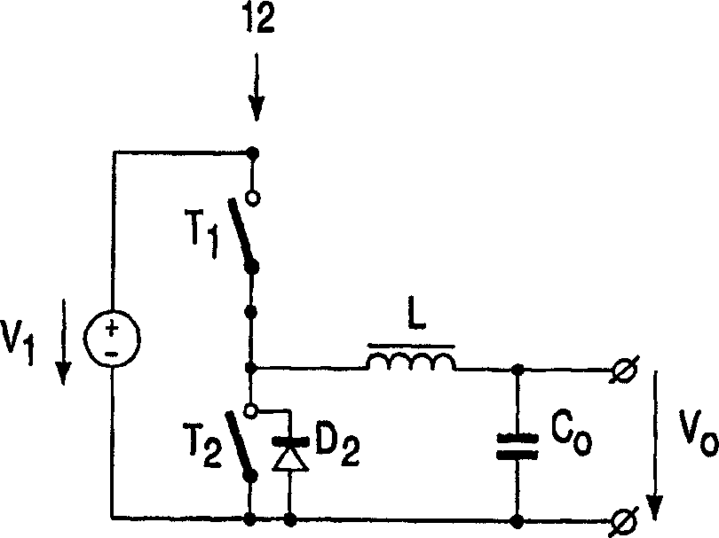
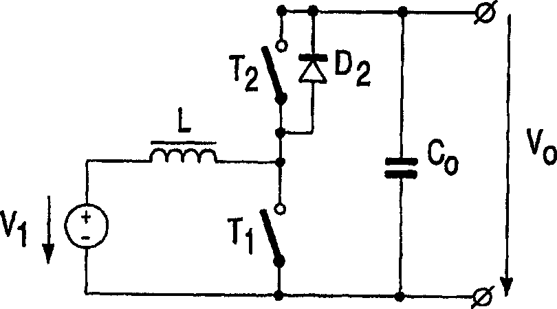
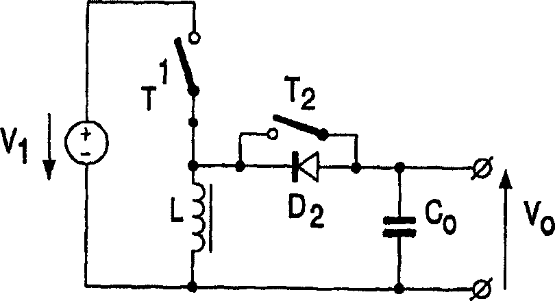
[0038] Figures 1a-1d shows a converter circuit according to a known layout: a buck converter ( Figure 1a ), boost converter ( Figure 1b ), buck-boost converter ( Figure 1c ) and the up-down converter ( Figure 1d ). Each converter circuit 10 takes the input voltage V i Converts the output voltage to the output V o . Each converter circuit 10 includes a first switching element T 1 , the second switching element T 2 and inductive element L. Freewheeling diode D 2 It is part of the freewheeling path for the current passing through the inductance element L. exist Figures 1a-1d In and freewheeling diode D 2 parallel arrangement of the second switching element T 2 as synchronous rectifiers, i.e. they are connected with D 2 synchronization, whereby in order to avoid losses due to large forward voltages, if there is no T 2 case diode D 2 If they are turned on, they are also turned on. .

[0039] In fact, the ideal representation is Figures 1a-1d T of the switch...


PUM


Abstract

In known converter circuits switching losses occur, which are caused by reverse-recovery currents of a freewheeling diode. To reduce said switching losses it is proposed by the invention to drive the switching elements such that, upon switching from the second to the first switching element, the timing is controlled in such a manner that the shoot through currents and the conduction of the freewheeling diode are kept at a low value or, better still, are precluded. As regards the control mechanism, it is proposed to turn on the first switching element later if shoot through currents occur, and to turn on the first switching element sooner if conduction of the freewheeling diode occurs. Here, a time of overlap may be provided during which both switching elements are simultaneously conducting. For the control mechanism, the voltage across a switching element can be used as a measured input value.

Description

technical field [0001] The invention relates to a converter circuit and a control method, and also relates to a driving device for the converter circuit. Background technique [0002] A converter circuit is employed to convert the input voltage to an output voltage. For DC / DC converter circuits in particular, various topologies are known, ie circuits in which the switches used in the circuit are driven appropriately in order to meet various needs. [0003] A known converter topology is the synchronous step-down converter (buck converter). On its input side, the buck converter comprises a half-bridge circuit with a first switching element (control) and a second switching element (synchronization), which half-bridge circuit is operated at an input DC voltage. The bridge arm connected between the switching elements includes an inductor after which a load is connected. For example, the switching elements are alternately driven by pulse cycle control. Buck converters are used...

Claims


Application Information

Patent Timeline
Patent Type & Authority Applications(China)
IPC IPC(8): H02M1/00H02M1/38H03K17/687
CPCH02M1/38H03K17/6871
Inventor T·G·托尔勒T·德鲍姆R·埃菲里奇
Owner KONINKLIJKE PHILIPS ELECTRONICS NV
Why Eureka
Try Eureka