High efficient marsh gas tank
A biogas digester, high-efficiency technology, applied in the direction of gas production bioreactors, waste fuels, etc., can solve the problems of poor mixing of fermentation materials, high production efficiency, easy to block floating covers, etc., to achieve high mixing and low operating costs The effect of less, more gas production
- Summary
- Abstract
- Description
- Claims
- Application Information
AI Technical Summary
Problems solved by technology
Method used
Image

Examples
Embodiment 1
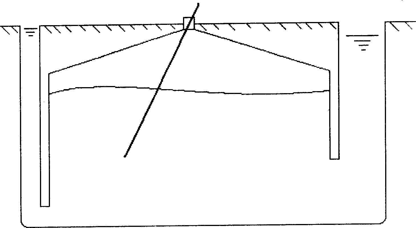
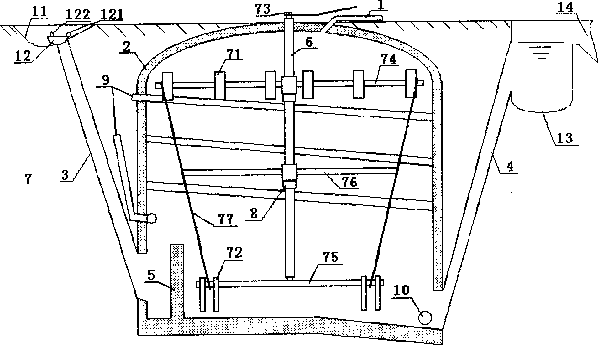
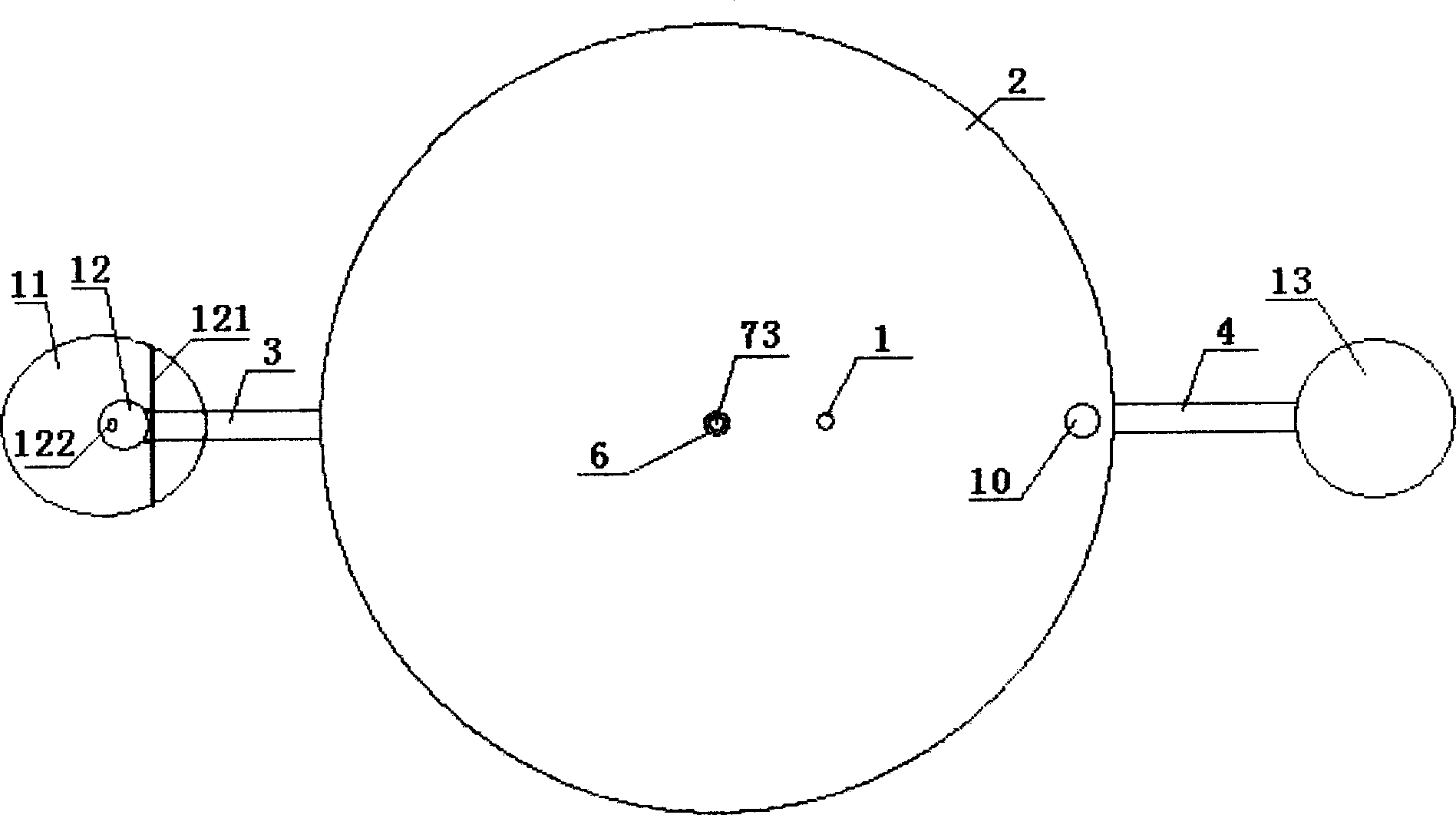
[0025] Embodiment one, such as figure 2 , 3 As shown in and 8, the high-efficiency biogas digester of the present invention is composed of a fermentation tank 2 with a trachea 1 at the top, a feed pipe 3 and a discharge pipe 4 connected to the fermentation tank 2 at the front and rear sides respectively, and the feed pipe 3 and the discharge pipe The pipes 4 are all inclined outward and upward, the lower end of the feed pipe 3 is connected to the feed port at the lower part of the side wall of the fermentation tank 2, the lower end of the discharge pipe 4 is connected to the discharge port at the lower end of the side wall of the fermentation tank 2, and the bottom of the fermentation tank 2 faces the discharge pipe 4 One side is inclined downward, and the fermentation tank 2 is equipped with a separator plate 5 near the feed inlet; a sleeve 6 extending into the fermentation tank 2 is fixed in the center of the upper cover of the fermentation tank 2, and the sleeve 6 is equip...
Embodiment 2
[0026] Embodiment two, such as Figure 4 , 5As shown in and 8, the high-efficiency biogas digester of the present invention is composed of a fermentation tank 2 with a trachea 1 at the top, a feed pipe 3 and a discharge pipe 4 connected to the fermentation tank 2 at the front and rear sides respectively, and the feed pipe 3 and the discharge pipe The pipes 4 are all inclined outward and upward, the lower end of the feed pipe 3 is connected to the feed port at the lower part of the side wall of the fermentation tank 2, the lower end of the discharge pipe 4 is connected to the discharge port at the lower end of the side wall of the fermentation tank 2, and the bottom of the fermentation tank 2 faces the discharge pipe 4 One side is inclined downward, and the fermentation tank 2 is equipped with a separator plate 5 near the feed inlet; a sleeve 6 extending into the fermentation tank 2 is fixed in the center of the upper cover of the fermentation tank 2, and the sleeve 6 is equipp...
Embodiment 3
[0027] Embodiment three, such as Image 6 , 7 As shown in and 8, the high-efficiency biogas digester of the present invention is composed of a fermentation tank 2 with a trachea 1 at the top, a feed pipe 3 and a discharge pipe 4 connected to the fermentation tank 2 at the front and rear sides respectively, and the feed pipe 3 and the discharge pipe The pipes 4 are all inclined outward and upward, the lower end of the feed pipe 3 is connected to the feed port at the lower part of the side wall of the fermentation tank 2, the lower end of the discharge pipe 4 is connected to the discharge port at the lower end of the side wall of the fermentation tank 2, and the bottom of the fermentation tank 2 faces the discharge pipe 4 One side is inclined downward, and the fermentation tank 2 is equipped with a separator plate 5 near the feed inlet; a sleeve 6 extending into the fermentation tank 2 is fixed in the center of the upper cover of the fermentation tank 2, and the sleeve 6 is equi...
PUM
 Abstract
Description
Claims
Application Information