Monolithic sputtering target assembly

A sputtering target and integral technology, applied in the direction of electrical components, discharge tubes, circuits, etc., can solve the problems of high cost, inability to completely ensure that pollution is controlled, and increase the extra time for manufacturing target components

Inactive Publication Date: 2005-10-26
CABOT CORP
View PDF14 Cites 11 Cited by
  • Summary
  • Abstract
  • Description
  • Claims
  • Application Information

AI Technical Summary

Problems solved by technology

However, such coatings can be very expensive and add additional time to the manufacture of the target assembly, furthermore, since such coatings may not be applied uniformly, or as the coatings are applied thick enough to resist the sputtering process, This approach does not fully ensure that contamination is under control

Method used


Image

  • Monolithic sputtering target assembly
  • Monolithic sputtering target assembly
  • Monolithic sputtering target assembly

Examples


Embodiment Construction

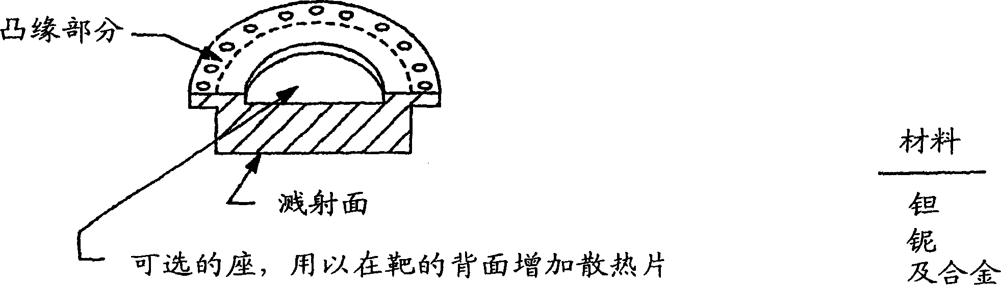
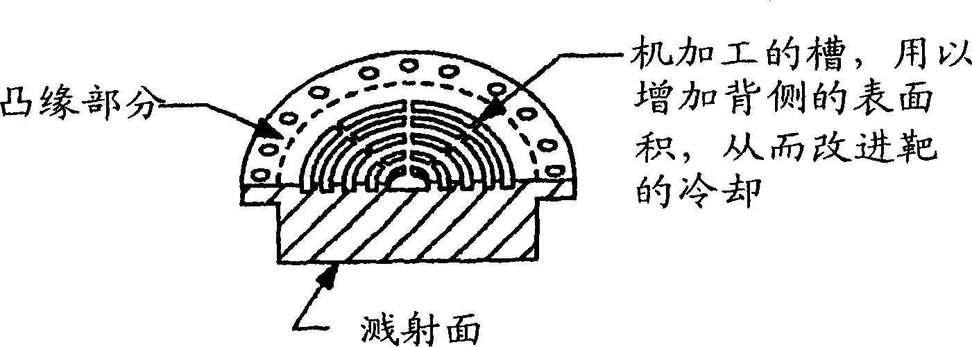
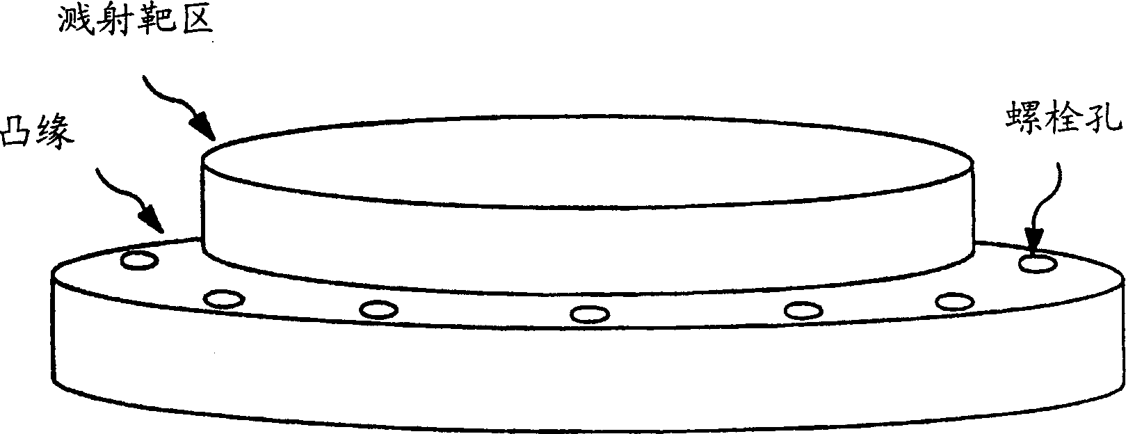
[0019] The present invention relates to a sputtering target assembly, which has unique advantages over conventional sputtering target assemblies. More specifically, in one embodiment of the invention, the invention relates to a monolithic sputtering target assembly. The monolithic sputtering target is a monolithic component or a monolithic structure made entirely of one and the same material, preferably a metal capable of being sputtered or corroded during deposition.

[0020] The term "monolithic" means a sputtering target assembly made from a single piece. There are no joints or seams in the target assembly that are created by joining separate components to form a conventional target assembly that bonds the backing plate to the sputtering target blank on to form a component. Another term that may be used to describe this embodiment is integral target assembly.

[0021] The material used for the monolithic sputtering target assembly can be any metal that can be sputtered o...


PUM

PropertyMeasurementUnit
particle sizeaaaaaaaaaa

Abstract

A monolithic sputtering target assembly having a one piece assembly made from the same material is disclosed. Also disclosed are other sputtering target assemblies which have a backing plate and a sputtering target blank wherein the backing plate is made from or contains a metal, such as a valve metal, cobalt, titanium, or alloys thereof. Methods of recycling target assemblies are further disclosed as well as unique methods of providing target assemblies to fabricators.

Description

technical field [0001] The present invention relates to a sputtering target and a sputtering target assembly and a manufacturing method thereof. The invention also relates to a method of using and recycling sputter targets and sputter target assemblies. Background technique [0002] In the field of sputtering applications, a sputtering target assembly typically has a sputtering target and a backing plate. For example, a metal target or metal target is bonded to a backing plate such as a backing plate flange assembly typically made of copper, aluminum or alloys thereof. Said binding process and structure of the target assembly not only increases the cost of the overall assembly, but also increases the weight and creates a risk of debonding of the target assembly during use. This risk of debonding is more prone to occur due to the continued development of the industry requiring the use of larger and larger targets. The reason for this phenomenon is that the thermal expansio...

Claims


Application Information

Patent Timeline
Patent Type & Authority Applications(China)
IPC IPC(8): C23C14/34
CPCH01J37/3491B22F2998/00C23C14/3407C23C14/3414H01J37/3426C22C1/04
Inventor 罗伯特·B·福特克里斯托弗·A·米哈卢克
Owner CABOT CORP
Why Eureka
Try Eureka