
Fluorescent tube with reflection shielding film on backward tube wall

A technology for fluorescent tubes and tubes, applied in the field of fluorescent tubes, can solve the problems of loss of reflective lighting function and effect, reduction, etc., and achieve the effects of easy popularization and application, high-efficiency reflective shielding function, and enhanced brightness

Inactive Publication Date: 2005-11-09
俞惠东
View PDF0 Cites 0 Cited by
  • Summary
  • Abstract
  • Description
  • Claims
  • Application Information

AI Technical Summary

Problems solved by technology

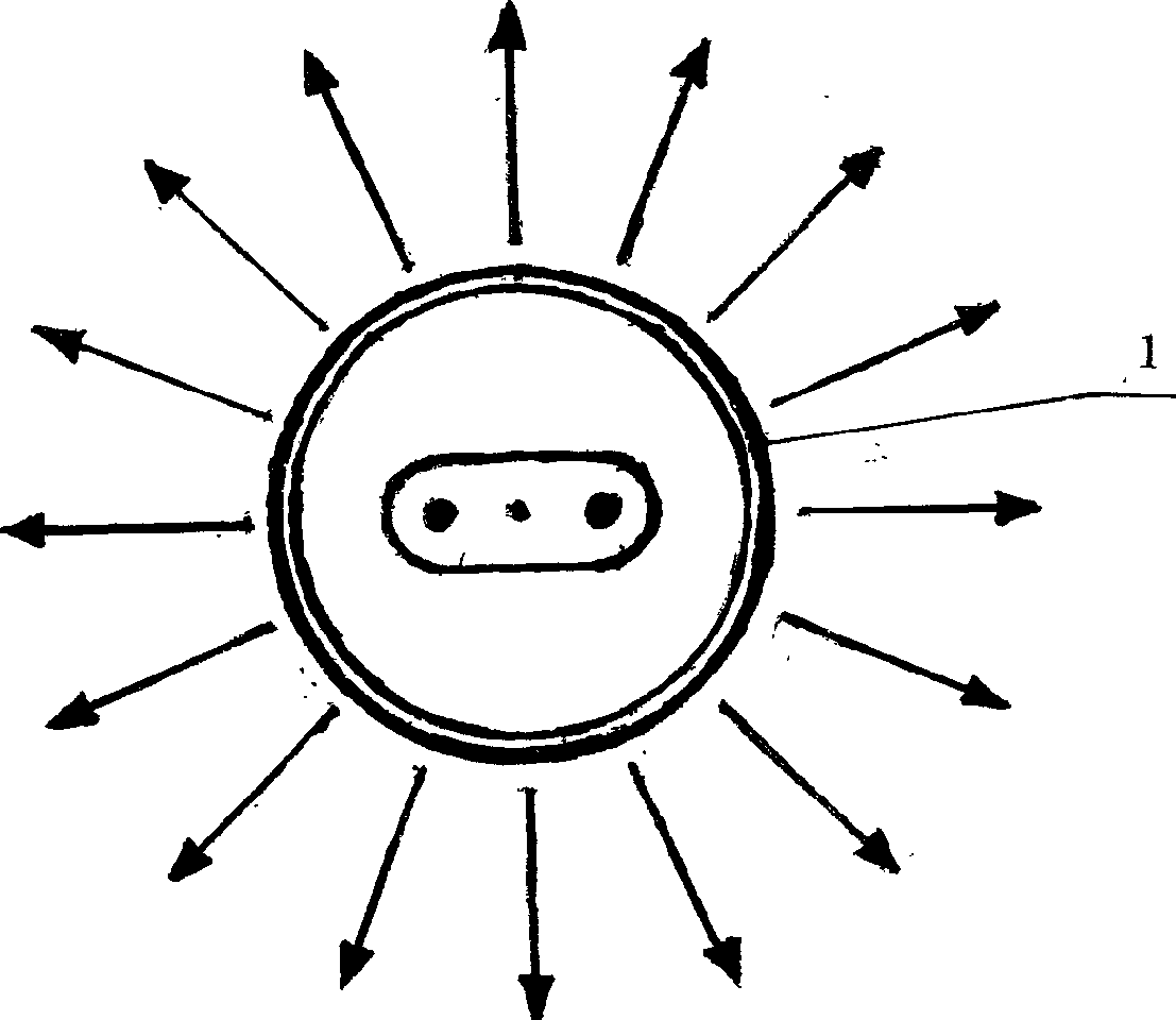
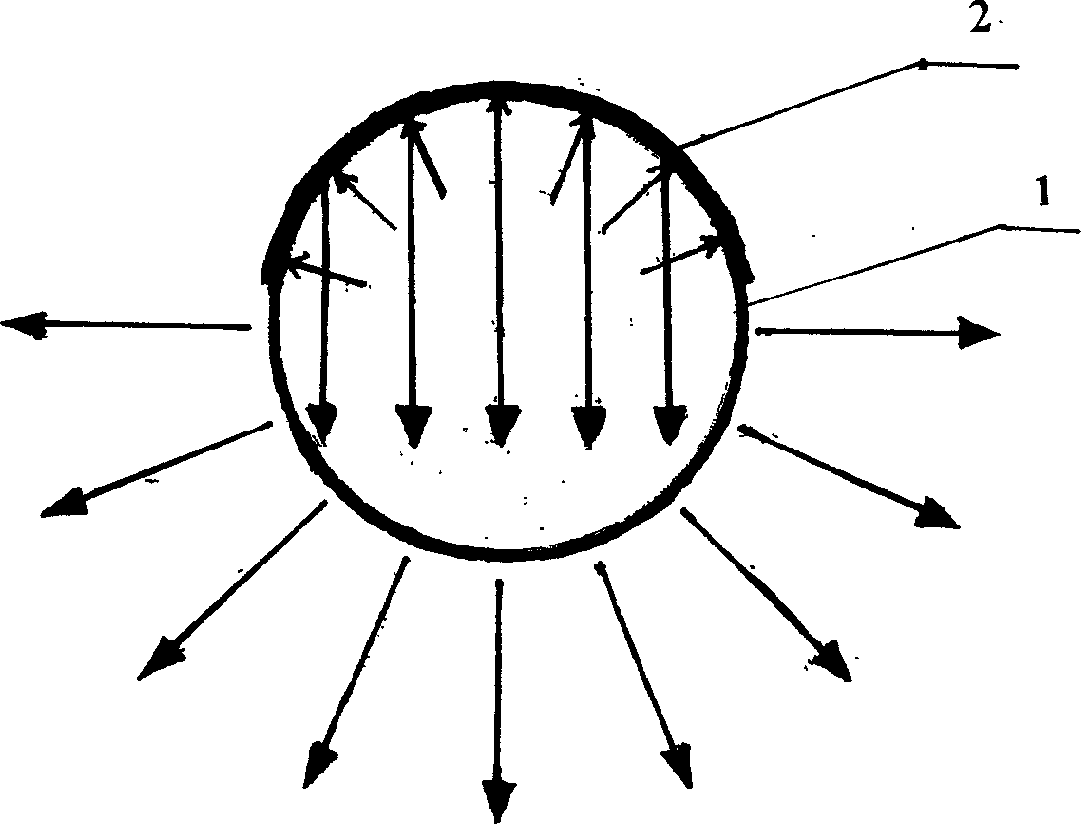
[0002] Fluorescent tubes used in actual production and life always have the outer surface of the tube wall with a width equal to or less than half of the circumference of the tube body facing away from the object to be illuminated, such as figure 1 As shown, the backlight it emits must rely on the reflective shielding layer set on the lampshade to be reflected into the forward light to assist the forward lighting. As time goes by, the dust accumulated on the outer surface of the lamp tube wall will absorb The dust or oxidation will gradually reduce or even lose the function and effect of reflective lighting

Method used

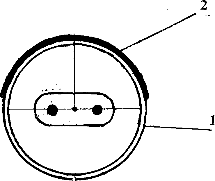

Image

  • Fluorescent tube with reflection shielding film on backward tube wall
  • Fluorescent tube with reflection shielding film on backward tube wall
  • Fluorescent tube with reflection shielding film on backward tube wall

Examples


Embodiment Construction

[0020] Below in conjunction with accompanying drawing and embodiment the present invention will be further described:

[0021] One of the most common installation methods for straight fluorescent tubes is: the lamp pin bracket is fixed in the direction of the ceiling, and when the front of the lamp tube body faces the direction of the lamp tube wall to illuminate the ground, the filament lead-out terminals and lamp pins at both ends of the lamp tube The jack is in a horizontal position, and the line of the vertical bisector of its filament terminal line coincides with the center line of the reflective shielding film set on the outer surface of the lamp tube wall. Such as image 3 As shown, as the uniform standard setting position of the reflective shielding film on the outer surface of the fluorescent tube wall facing away from the universal type of fluorescent tube, it is also most suitable for the lamination process of the straight fluorescent tube to paste the mirror reflec...


PUM


Abstract

The invention discloses a fluorescent lamp tube with reflection shielding film on back ward tube wall for raising lighting brightness, and maintaining high efficiency reflection shield function, anti-dust, non-oxidization, also provide the corresponding mirror surface reflection shield coating, lamp pipe wall anti-adhesive agent. The mirror surface reflection shield aluminum plastic compound adhesive film and fluorescent lamp pin capable of steering change location, adjusting lamp pipe wall illumination angle. This invention is suitable for improving brightness of every kind of fluorescent tube the operation is simple, the effect is obvious, also can mechanical flowline production low cost, no pollution, and easy application.

Description

technical field [0001] The invention relates to a fluorescent lamp tube, in particular to a lamp tube wall of the fluorescent lamp tube and its implementation material. Background technique [0002] Fluorescent tubes used in actual production and life always have the outer surface of the tube wall with a width equal to or less than one-half of the circumference of the tube body facing away from the object to be illuminated, such as figure 1 As shown, the backlight it emits must rely on the reflective shielding layer set on the lampshade to be reflected into the forward light, so as to assist the forward lighting. The dust or oxidation will gradually reduce or even lose the function and effect of reflective lighting. Contents of the invention [0003] The purpose of the present invention is to overcome the deficiencies of the prior art, to provide a reflective shielding film directly on the outer surface of the fluorescent lamp t...

Claims


Application Information

Patent Timeline
Patent Type & Authority Applications(China)
IPC IPC(8): H01J61/35
Inventor 俞惠东
Owner 俞惠东
Learn More