Locking ring pole type hydraulic tyre vulcanizing machine pressurize from inside

A tire vulcanization and hydraulic technology, which is applied to the field of internal pressure lock-ring column hydraulic tire vulcanizers, can solve problems such as the influence of mold life, increase manufacturing costs, and difficult maintenance, so as to reduce manufacturing costs and maintenance costs, and improve tires. Vulcanization quality, improve the effect of mold regulation and pressure regulation

Active Publication Date: 2005-11-16
福建天华智能装备有限公司
View PDF0 Cites 8 Cited by
  • Summary
  • Abstract
  • Description
  • Claims
  • Application Information

AI Technical Summary

Problems solved by technology

[0003] The mechanical tire vulcanizing machine generally adopts a four-bar linkage mechanism. It uses the four-bar linkage mechanism to perform mechanical movement to realize the tightness of the upper and lower molds. After pressurization and heating, the tire is vulcanized in the mold. Its disadvantages are as follows: The structure is complex, such as the beam base structure is bulky, and includes a crank gear transmission mechanism, etc.; the second is poor rigidity, such as the beam and the four-link are easily deformed; the third is the centering accuracy is low; the fourth is that the mold life is long due to the deformation of the beam Affected; Fifth, the long time of mold opening and closing affects the efficiency
[0004] Existing hydraulic tire vulcanizing machines generally adopt a frame structure with upper and lower beams fixed; some also use lower beams and side plates to be relatively fixed, while the upper beam can move up and down in the guide grooves of the two side plates. At the same time, the upper beam is fixed in the left and right side plate holes with bolts, thus forming a closed frame system. This structure is essentially consistent with the frame structure; their pressurized cylinders are usually devices. On the base, pressure is applied upwards through the plunger, and the pressure acts on the lower mold through the lower supporting plate to achieve the purpose of tightening the mold, thus realizing the vulcanization process of the tire in the mold. During this process, the frame or bracket has to bear Clamping force, therefore, the beams, base and other components in the frame must be made larger in order to withstand the clamping force, for this reason, the whole equipment must be made relatively large, heavy and complicated, thereby increasing the product manufacturing cost
[0005] There is also a lock ring cylinder structure, which includes upper and lower cylinders, and the upper and lower cylinders are connected by lock rings. Because its upper cylinder is usually welded with the upper beam to form an integrated structure , the lower cylinder is usually welded with the base to form an integrated structure, and the pressurized oil cylinder is installed in the base, and the cylinder is pressurized from the outside. In this way, when the pressure is closed, the upper beam and The base will bear the clamping force. Therefore, the upper beam, the base and other components must be made larger so as to withstand the clamping force, which makes the whole equipment larger, heavy and complicated. On the other hand, this This type of pressurized oil cylinder has a complex and huge structure and is installed in the abdominal cavity of the base, which is difficult to maintain and also makes it impossible to install multiple pressurized oil cylinders, so that the pressure on the cylinder cannot be more uniform

Method used


Image

  • Locking ring pole type hydraulic tyre vulcanizing machine pressurize from inside
  • Locking ring pole type hydraulic tyre vulcanizing machine pressurize from inside
  • Locking ring pole type hydraulic tyre vulcanizing machine pressurize from inside

Examples


Embodiment 1

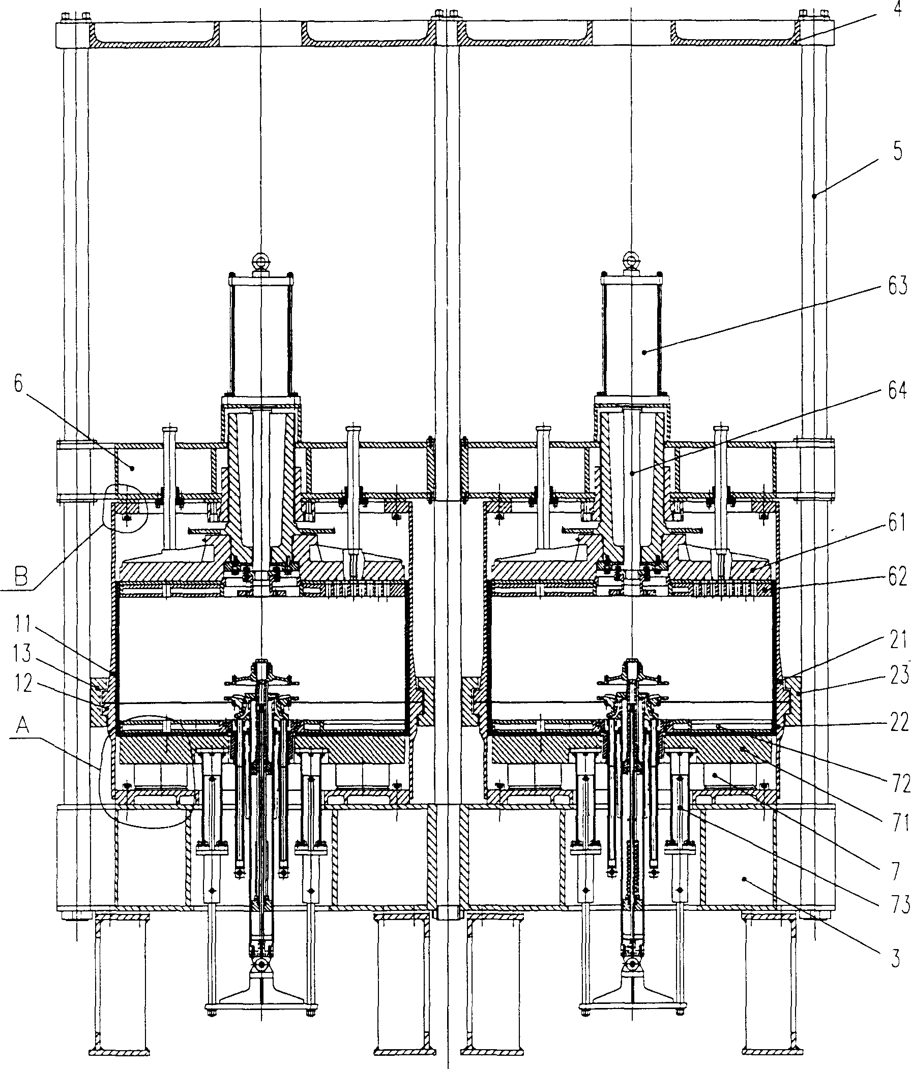
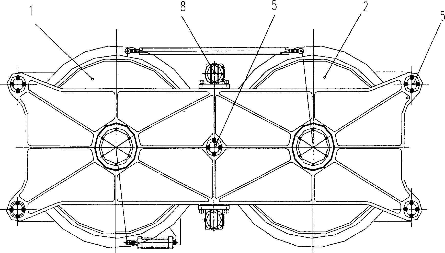
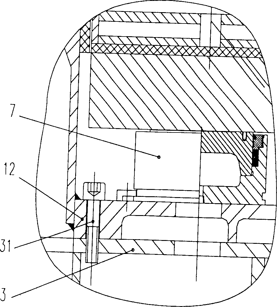
[0033] Embodiment one, see Figure 1 to Figure 5As shown, a hydraulic tire vulcanizer of the present invention is a hydraulic tire vulcanizer with a five-column dual-mode structure, which includes two cylinders, namely the left cylinder 1 and the right cylinder 2, and a base 3. The upper support plate 4 and five columns 5, the upper end of each column 5 is fixedly connected with the upper support plate 4, and the lower end is fixedly connected with the base 3 respectively, and the five columns 5 are distributed at the four corners and the middle position ; Left cylinder 1 is provided with left upper cylinder 11, left lower cylinder 12, right cylinder 2 is provided with right upper cylinder 21, right lower cylinder 22, and left lower cylinder 12, right lower cylinder 22 its respective bottom plate adopts respectively The screw 31 is fixedly connected with the base 3, and six mold clamping pressurization cylinders 7 are respectively fixed on the bottom plates of the left lower c...

Embodiment 2

[0036] Embodiment two, see Figure 6 As shown, the present invention is a five-column double-mode vulcanizing machine with internally pressurized locking ring column type hydraulic tire vulcanizing machine. Instead, it is mounted on both sides, that is, the left and right positions.

Embodiment 3

[0037] Embodiment three, see Figure 7 As shown, a kind of internal pressurized locking ring column type hydraulic tire vulcanizing machine of the present invention is a four-column double-mode vulcanizing machine. The front and back of the side are respectively socketed with a column 5 slidingly, and four columns 5 are on the four corner positions of the elevating beam 6.


PUM


Abstract

A hydraulic sulfurizing machine for tyre is composed of one or two barrel bodies consisting of upper and lower barrel bodies for closing the mould, base, top supporting plate, 4 or 5 or 8 vertical columns between said top supporting plate and base, multiple pressing cylinders fixed to the base plate of lower barrel bodies, transverse lift beam linking with said vertical column in sleeve joint mode, and two lift cylinders arranged at both ends of said transverse lift beam.

Description

technical field [0001] The invention relates to a tire vulcanizing equipment, in particular to an inner pressurized locking ring column type hydraulic tire vulcanizing machine. Background technique [0002] Tire curing presses are usually divided into two categories: mechanical and hydraulic. [0003] The mechanical tire vulcanizing machine generally adopts a four-bar linkage mechanism. It uses the four-bar linkage mechanism to perform mechanical movement to realize the tightness of the upper and lower molds. After pressurization and heating, the tire is vulcanized in the mold. Its disadvantages are as follows: The structure is complex, such as the beam base structure is bulky, and includes a crank gear transmission mechanism, etc.; the second is poor rigidity, such as the beam and the four-link are easily deformed; the third is the centering accuracy is low; the fourth is that the mold life is long due to the deformation of the beam Affected; Fifth, the long time of openin...

Claims


Application Information

Patent Timeline
Patent Type & Authority Applications(China)
IPC IPC(8): B29C35/02
Inventor 陈午生张锦芳张正罗
Owner 福建天华智能装备有限公司
Why Eureka
Try Eureka