Filtering speed reducer

A deceleration mechanism and eccentric technology, applied in the direction of transmission, belt/chain/gear, mechanical equipment, etc., can solve the problems of easy fatigue damage, small power transmission of planetary reducer, thin wall and easy damage, etc., and achieve relatively small size and large deceleration ratio, compact structure

Inactive Publication Date: 2005-11-23
CHONGQING UNIV
View PDF0 Cites 5 Cited by
  • Summary
  • Abstract
  • Description
  • Claims
  • Application Information

AI Technical Summary

Problems solved by technology

Such as aviation, aerospace, transportation and other fields, a reducer with large reduction ratio, compact structure, light weight and high efficiency is required. Under this requirement, the volume of the worm reducer is too large, and the mechanism of the cycloid reducer is too large. Complicated, the power transmitted by the planetary reducer is too small, etc., the harmonic reducer has the disadvantages of flexible splines constantly deforming at high frequencies, easy to fatigue damage, and thin walls are easy to damage, etc.
In other words, there is currently no reducer that meets the above industry requirements.

Method used


Image

  • Filtering speed reducer
  • Filtering speed reducer
  • Filtering speed reducer

Examples


Embodiment Construction

[0010] Below in conjunction with accompanying drawing and embodiment the present invention will be further described:

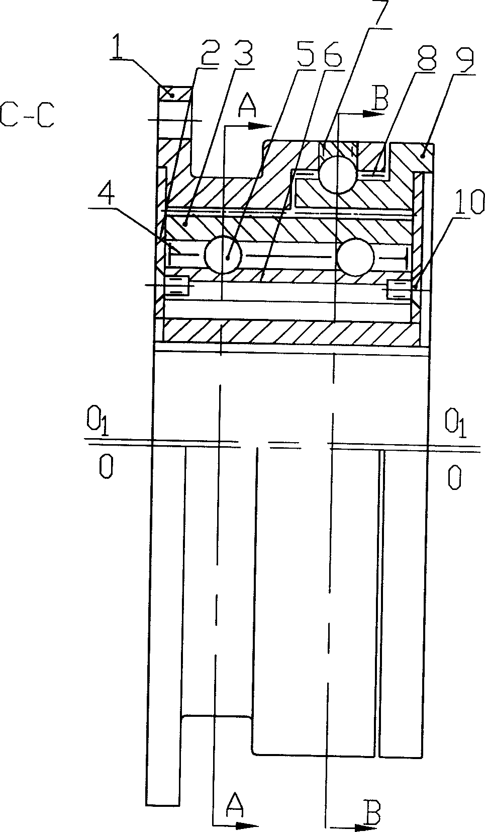
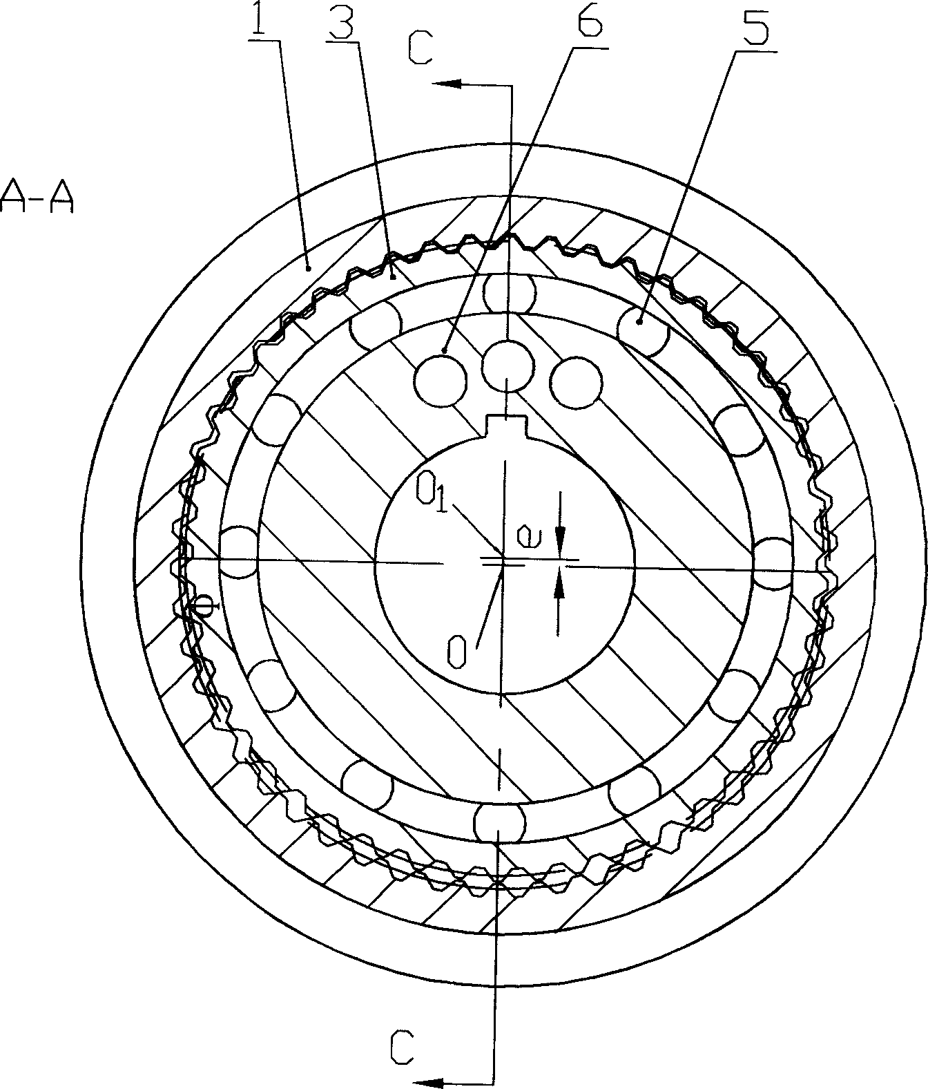
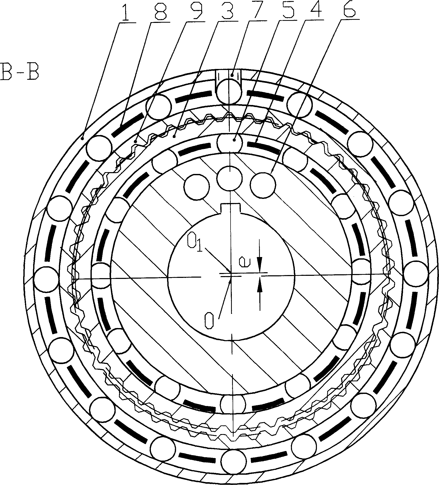
[0011] The filtering speed reducer involved in the present invention is fixed on the machine body or the motor by the flange plate on the internal gear 1 through screws, so the internal gear 1 remains motionless. The shaft of the motor drives the eccentric wheel 6 to rotate at a high speed through the flat key. Output low-speed rotation by output internal gear 9. The filter reducer is composed of an eccentric reduction mechanism, a filter spline mechanism and a three-way thrust bearing. Eccentric reduction mechanism such as figure 1 A-A section in and figure 2 As shown, it is composed of eccentric wheel 6, rolling bearing, cylindrical gear 3 and internal gear 1. The outer circle of the eccentric wheel doubles as the inner ring surface of the rolling bearing. Therefore, the outer raceway of the eccentric wheel is distributed on the eccentric, and its arc c...


PUM


Abstract

The invention relates to a filtering decelerator which comprises: an eccentric decelerating mechanism, a filtering spline mechanism and a three-direction end thrust bearing. The eccentric decelerating mechanism comprises: an eccentric wheel (6), a rolling bearing, a cylindrical gear (3) and an inner gear (1); the filtering spline mechanism comprises an eccentric wheel (6), a steel ball (5), a cylindrical gear (3) and an output inner gear (9); the three-direction end thrust bearing connect the inner gear (1) with the output inner gear (9), use the eccentric wheel to realize the deceleration of a pair of gear wheel that short of tooth tolerance; the filtering spline mechanism comprises a group of gear wheels that have the same tooth number and diameter, it filters the high order revolution wave and output low frequency rotary.

Description

technical field [0001] The invention belongs to a mechanical transmission device in the field of mechanical engineering. Background technique [0002] At present, there are many kinds of reducers, each with its own characteristics, which are widely used in various industries. However, with the development of production technology, new needs often arise. Such as aviation, aerospace, transportation and other fields, a reducer with large reduction ratio, compact structure, light weight and high efficiency is required. Under this requirement, the volume of the worm reducer is too large, and the mechanism of the cycloid reducer is too large. Complicated, the power transmitted by the planetary reducer is too small, etc., the harmonic reducer has the disadvantages of continuous high-frequency deformation of the flexible spline, easy fatigue damage, and thin wall is easy to damage. That is to say, there is currently no reducer that meets the above-mentioned industrial requirements...

Claims


Application Information

Patent Timeline
Patent Type & Authority Applications(China)
IPC IPC(8): F16H37/12
Inventor 梁锡昌王家序
Owner CHONGQING UNIV
Why Eureka
Try Eureka