
Illumination device and projector

A lighting device and light source technology, applied in projection devices, image reproducers using projection devices, color TVs, etc., can solve problems that are not clearly stated and not clearly stated, and achieve the effect of simple composition

Inactive Publication Date: 2005-11-23
SEIKO EPSON CORP
View PDF2 Cites 3 Cited by
  • Summary
  • Abstract
  • Description
  • Claims
  • Application Information

AI Technical Summary

Problems solved by technology

[0005] However, in Patent Document 1, although the formation of the optical filter portion and the movement of the optical filter corresponding to the focal position emitted by the integrating lens have been described, in which direction and how much the optical filter should be moved, then not specified
[0006] In addition, the specific configuration of the optical filter and the mechanism for moving the optical filter is not described, and how to switch between high-brightness image display and high-chromaticity image display is not clearly stated.

Method used


Image

  • Illumination device and projector
  • Illumination device and projector
  • Illumination device and projector

Examples


no. 2 Embodiment approach

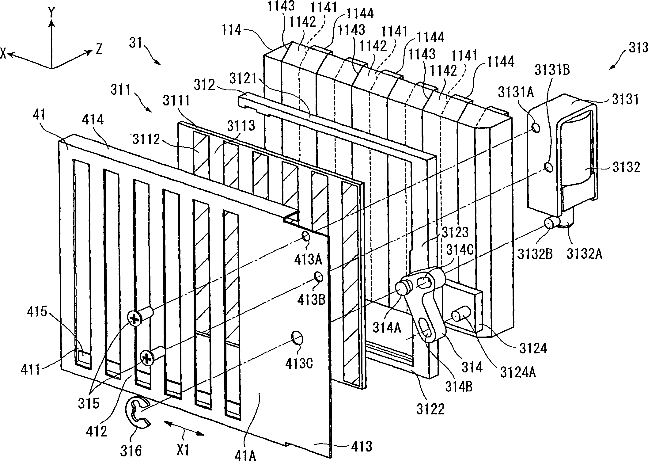
[0146] Next, a projector according to a second embodiment of the present invention will be described. The second embodiment differs from the first embodiment in the structure of the optical correction device as described below. The structure of other parts is the same as that of the first embodiment. In addition, in the following description, the same reference numerals are attached to the same or substantially the same parts as those already described, and descriptions thereof are omitted.

[0147] Figure 10 A perspective view of the light correction device 32 and the mask 42 observed from the back side (light exit side) is shown in .

[0148] The projector of the second embodiment, such as Figure 10 As shown, a mask 42 and a light correction device 32 are provided, wherein the light correction device 32 has an optical filter 311 , a holder 322 and a filter driving mechanism 323 .

[0149] Like the mask 41 of the first embodiment, the mask 42 is arranged at the front st...

no. 3 Embodiment approach

[0158] Next, a projector according to a third embodiment of the present invention will be described. The third embodiment differs from the first and second embodiments in the arrangement pattern of the filter films in the optical filter of the light correction device. The structure of other parts is the same as that of the first or second embodiment. In addition, in the following description, the same reference numerals are assigned to the same or substantially the same parts as those already described, and descriptions thereof will be omitted.

[0159] The optical correction device 31 provided in the projector of the third embodiment includes an optical filter 331 instead of the optical filter 311 of the first and second embodiments. This optical filter 331 is configured such that, in the case of converting an incident light beam, a filter can be inserted with respect to the light beam incident on the outer edge of the optical filter 331, and a filter can be inserted with re...


PUM


Abstract

An illumination device includes: a light source; a polarization converter (114) that converts a light beam irradiated by the light source into a substantially uniform linear polarized light, the polarization converter (114) being slanted relative to a central axis of the light beam irradiated by the light source and including a plurality of polarization-separating films (1141) and a plurality of light reflection films (1143) alternately arranged in a direction substantially orthogonal to the central axis of the light beam irradiated by the light source; an optical filter (311) provided between the light source and the polarization converter (114) and having a plurality of optical conversion layers, which are formed striped with the pitch thereof corresponding to the arrangement of the polarization-separating films (1141) to optically convert the incident light beam; a holder frame (312) that holds the optical filter (311); and a filter-driving mechanism (313) that moves the holder frame (312) in a direction in which the polarization-separating films (1141) are arranged.

Description

technical field [0001] The present invention relates to a lighting device and a projector provided with an optical filter for converting the brightness and / or color tone of a light beam emitted from a light source. Background technique [0002] In the past, projectors were mostly used for presentations in conferences, academic societies, and exhibitions. Such a projector is mainly used as a data projector for displaying characters, graphics, and the like. In addition, since projectors have been rapidly popularized in recent years, they are often used as projectors for home theaters, such as watching movies at home. [0003] However, in the case of displaying characters and the like, high-brightness image display is required for data projectors. On the other hand, home theater projectors are required to display high-color images (high-chroma images) with high color reproducibility in order to display images such as television and movies. In this way, regarding the image qu...

Claims


Application Information

Patent Timeline
IPC IPC(8): G02B5/00G02B27/28H04N9/31
CPCH04N9/3197H04N9/315G02B27/285G02B5/005G02B27/283
Inventor 西田和弘百濑明
Owner SEIKO EPSON CORP
Learn More