Capacitor and method of connecting the same

A technology of capacitors and external connection terminals, applied in the direction of capacitors, electrolytic capacitors, capacitor terminals, etc., can solve the problems of shortening the life of capacitors, deteriorating rubber parts, reducing sealing performance, etc., to suppress chemical deterioration, reduce contact resistance, and improve reliability. Effect

Inactive Publication Date: 2005-11-23
PANASONIC CORP
View PDF3 Cites 12 Cited by
  • Summary
  • Abstract
  • Description
  • Claims
  • Application Information

AI Technical Summary

Problems solved by technology

[0017] The acid component that drives the electrolyte moves along the inner surface of the metal case, and deteriorates the rubber portion that is in contact with the open end portion, so that the sealing performance is reduced
[0018] When the driving electrolyte leaks to the outside in this way, this situation not only causes a problem of shortening the life of the capacitor, but also causes a problem that when the driving electrolyte is deposited on the positive and negative parts of the wiring pattern of the printed circuit board in a bridging manner, due to leakage to The external driving electrolyte has ion-conducting properties and causes the failure of the circuit

Method used


Image

  • Capacitor and method of connecting the same
  • Capacitor and method of connecting the same
  • Capacitor and method of connecting the same

Examples


no. 1 example

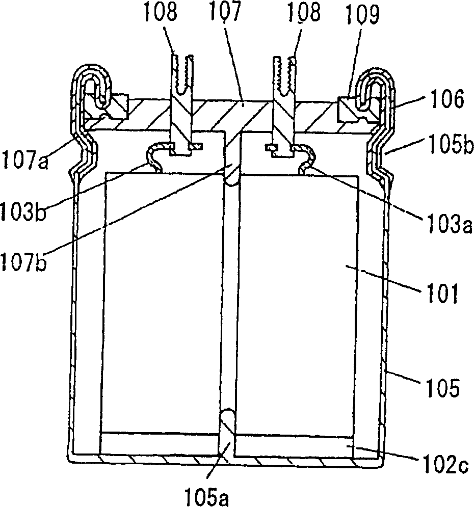
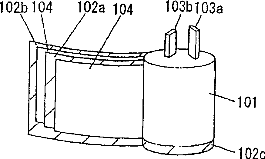
[0080] figure 1 is a sectional view showing the structure of the first embodiment of the capacitor of the present invention, and figure 2 is an expanded perspective view of the capacitor element used in this capacitor. exist figure 1 , reference numeral 101 indicates a capacitor element, and as figure 2 As shown, by respectively connecting the lead wires 103a and 103b with a pair of electrodes 102a and 102b, and then winding these electrodes into a roll with the isolation layer 4 disposed therebetween in such a way that one end surface 102c of an electrode 102b protrudes into a roll. Capacitor element 101 . Polarizable electrodes each composed of a mixture including at least activated carbon, a binder, and a conductive agent are formed on the electrode pairs 102a and 102b, respectively.


PUM


Abstract

A large capacity capacitor of which driving electrolyte does not leak to the outside even when used in high-temperature, high-humidity conditions. A capacitor has a hollow capacitor element (1) constructed by rolling a pair of flat plate-like electrodes (2a, 2b) with a separator (4) in between, a bottomed tubular metallic case (5) for receiving the capacitor element (1) together with a driving electrolyte, and a sealing plate (7), with external connection terminals (8), for sealing the opening of the metallic case (5). A rubber-like elastic body (9) is provided on the peripheral edge of a surface of the sealing plate (7), an electric insulation layer (6) covering at least portion from an opening edge of the metallic case (5) to a recess (5b) for fixing the sealing plate (7) is provided, and the elastic body (9) is pressed at the opening edge portion of the metallic case (5).

Description

technical field [0001] The present invention relates to capacitors of high capacitance used in various electronic devices and methods of connecting such capacitors. Background technique [0002] has been proposed, for example in Figure 18 and 19 The electric double-layer capacitor thus constructed as shown in is used as a capacitor with large capacitance. like Figure 18 As shown, in the electric double layer capacitor, the capacitor element 31 is accommodated in a metal case 36 with a closed bottom, and after injecting the driving electrolyte into the capacitive element 31, the capacitor element 31 is put into the metal case with a closed bottom 36, and the opening part is sealed by the opening sealing assembly 37. The outside of the metal case 36 is covered with a cover 38 made of synthetic resin. [0003] like Figure 19 As shown, in the capacitor element 31, sheet-like polarizable electrodes 32a and 33a each formed by mixing and stirring together, for example, activ...

Claims


Application Information

Patent Timeline
Patent Type & Authority Applications(China)
CPCY02E60/13
Inventor 三浦照久官崎良夫
Owner PANASONIC CORP
Why Eureka
Try Eureka