Three-sensor style encoder

A sensor and encoder technology, applied in the field of photoelectric sensing, can solve the problems of low precision, high processing cost, poor anti-interference of the encoder, etc., and achieve the effect of high precision

Inactive Publication Date: 2005-12-07
威海华东电源有限公司
View PDF0 Cites 11 Cited by
  • Summary
  • Abstract
  • Description
  • Claims
  • Application Information

AI Technical Summary

Problems solved by technology

[0007] In order to overcome the technical deficiencies of existing encoders such as poor anti-interference, low precision, high processing cost, and limited scope of application, the present invention provides a three-sensor encoder, which uses a magnetic sensor fixed on the circumference of the stator to sense and fix The change of magnetic field intensity caused by the rotation of the magnet on the shaft outputs voltage signals with different phase changes, and the voltage value is used to judge the rotation angle of the shaft. This type of sensor can realize high-precision measurement of rotation speed and absolute position

Method used


Image

  • Three-sensor style encoder
  • Three-sensor style encoder

Examples


Embodiment Construction

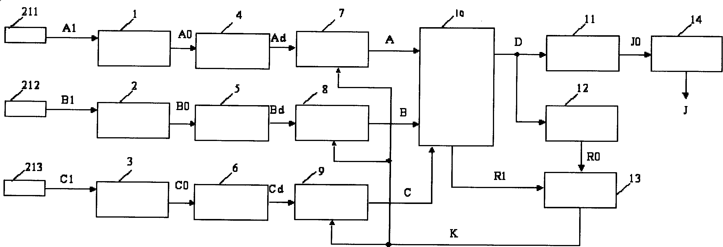
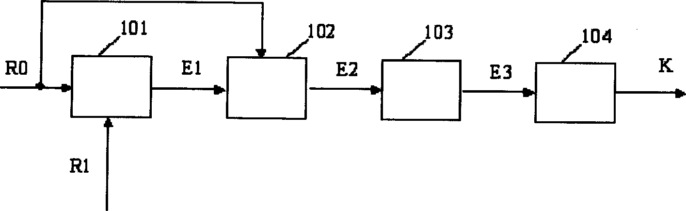
[0015] exist figure 1 In the quadrant position, three magnetic sensors are equidistantly arranged on the same circle, the angle between two adjacent sensors is 120°, and the output signal (A1) of the magnetic sensor (211) is connected to the amplifier (1) , the output signals (B1), (C1) of the other two magnetic sensors (212), (213) are respectively connected to the amplifier (2) and the amplifier (3), and the three amplifiers (1), (2), (3) The three output signals (A0), (B0), (C0) are respectively connected to the input ends of three AD converters (4), (5), (6), and the three AD converters (4), (5), Three output signals (Ad), (Bd), (Cd) of (6) are respectively connected to an input end of three multipliers (7), (8), (9), three multipliers (7), ( 8), three output signals of (9) connect the input end of synthesizer (10), the output signal (K) of coefficient corrector (13) connects another input end of three multipliers respectively, synthesizer (10) The output signal (D) of ...


PUM


Abstract

This invention relates to the photoelectric sensor technology characterizing that three magnetic sensors are set uniformly spaced on a same circumference at the quadrant position, the output signals of them are connected with an amplifier separately, the output signals of three amplifiers are connected with an AD converter connected with a multiplier, the output signal of a factor corrector is connected with the other input end of the multiplier, the output signal of which is connected with the input of a synthesizer, the output signal of which is taken as the input of the first and second storages, the other output signals of the synthesizer and the second storage is connected with the input of a factor corrector, the output signal of the first storage is connected with an angle converter.

Description

Technical field [0001] The invention belongs to the technical field of photoelectric sensing, in particular to a magnetic encoding circuit capable of measuring the rotation angle of a shaft. Background technique [0002] Rotary photoelectric encoder is a speed and displacement sensor integrating optical, mechanical and electrical technologies. When the encoder shaft drives the code disc to rotate, the light emitted by the light-emitting element passes through the open and dark areas of the code disc (or circular grating and indicating grating), and is divided into intermittent light and received by the receiving element to generate an initial signal. After the signal is processed by the subsequent circuit, a pulse signal is output. Photoelectric encoders have experienced a development process from incremental to absolute. [0003] When the shaft of the incremental encoder rotates, it drives the grating disk to rotate. The light emitted by the light-emitting element is cut ...

Claims


Application Information

Patent Timeline
IPC IPC(8): G01D5/347
Inventor 郝双晖郝明晖
Owner 威海华东电源有限公司
Why Eureka
Try Eureka