Eureka AIR delivers breakthrough ideas for toughest innovation challenges, trusted by R&D personnel around the world.

Carbon nano tube field emission device and preparation method thereof

一种碳纳米管、碳纳米管阵列的技术,应用在场发射装置及其制备领域,能够解决发射体易损坏、碳纳米管与基板结合不牢固等问题,达到均匀发射端、减少电屏蔽效应、降低起始电压的效果

Active Publication Date: 2005-12-07
TSINGHUA UNIV +1
View PDF1 Cites 6 Cited by
  • Summary
  • Abstract
  • Description
  • Claims
  • Application Information

AI Technical Summary

Problems solved by technology

[0007] In order to solve the technical problem that the carbon nanotubes are not firmly bonded to the substrate in the carbon nanotube field emission device of the prior art, and the carbon nanotubes are easily pulled out by the electric field force when the field emission current is relatively large, thereby causing the emitter to be easily damaged, the present invention The first purpose is to provide a carbon nanotube field emission device with good electrical contact between carbon nanotubes and the substrate, firm combination, undamaged emitter, and uniform and stable emission.

Method used


Image

  • Carbon nano tube field emission device and preparation method thereof
  • Carbon nano tube field emission device and preparation method thereof
  • Carbon nano tube field emission device and preparation method thereof

Examples


Embodiment Construction

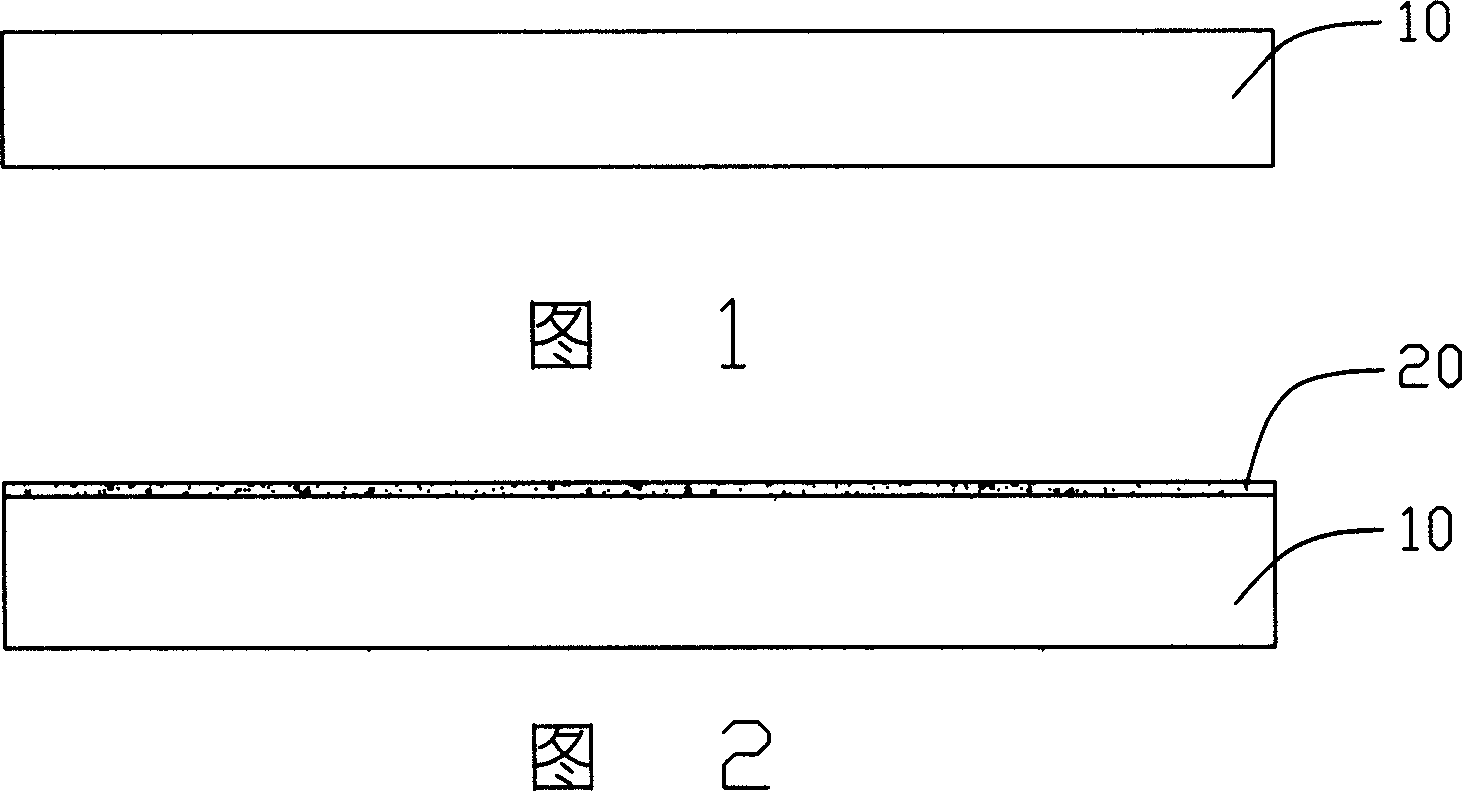
[0022] The carbon nanotube field emission device and preparation method thereof provided by the present invention are described below in conjunction with the accompanying drawings:

[0023] Such as Figure 5 As shown, the carbon nanotube field emission device 100 provided by the present invention includes a substrate 10, a catalyst layer 20 formed on the upper surface of the substrate 10, a carbon nanotube array 30 formed on the catalyst layer 20, and a carbon nanotube array 30 injected into the carbon nanotube The adhesive 40 in the array 30 is polycondensed after being dried to fix the carbon nanotube array 30 on the substrate 10 . Wherein, the top of the carbon nanotube array 30 is processed by laser, the adhesive 40 is removed, the top of the carbon nanotube array 30 is exposed to the adhesive 40, and is not covered by the adhesive, and the tops of the carbon nanotubes or carbon nanotube bundles are not mutually connected. winding.

[0024] In this embodiment, the substr...


PUM

PropertyMeasurementUnit
wavelengthaaaaaaaaaa
lengthaaaaaaaaaa
currentaaaaaaaaaa

Abstract

A carbon nano tube field emission device and preparation, which contains a substrate and at least carbon nano tube array formed on substrate, binding agent is infiltrated in carbon nano tube whose top is outer the binding agent which fixing the carbon nano tube on substrate and preventing it being drawn out from substrate by electric field force, said carbon nano tube field emission device is adaptive for vacuum electronic source device especially the cathode of field emission plane display device.

Description

【Technical field】 [0001] The invention relates to a field emission device and a preparation method thereof, in particular to a carbon nanotube field emission device and a preparation method thereof. 【Background technique】 [0002] Carbon nanotubes are a new type of carbon material, which was discovered by Japanese researcher Iijima in 1991, see "Helical Microtubules of Graphic Carbon", Iijima, Nature, vol.354, p56 (1991). Carbon nanotubes have excellent electrical conductivity, and they have a tip surface area that is almost close to the theoretical limit (the smaller the tip surface area, the more concentrated the local electric field), so carbon nanotubes are the best known field emission materials. The extremely low field emission open electric field (about 2 volts / micron) can transmit a large emission current density, and the emission current is extremely stable, so it is very suitable as an emission element of a field emission display. [0003] The carbon nanotube fiel...

Claims


Application Information

Patent Timeline
Patent Type & Authority Applications(China)
IPC IPC(8): H01J1/02H01J1/304H01J9/02
CPCH01J2201/30469H01J1/304B82Y10/00H01J9/025
Inventor 刘宇明刘亮范守善
Owner TSINGHUA UNIV
Why Eureka
Eureka Blog
Learn More