Oil ring
A technology of oil ring and ring rail, which is applied to piston rings, mechanical equipment, engine components, etc.
- Summary
- Abstract
- Description
- Claims
- Application Information
AI Technical Summary
Problems solved by technology
Method used
Image
Examples
no. 1 example
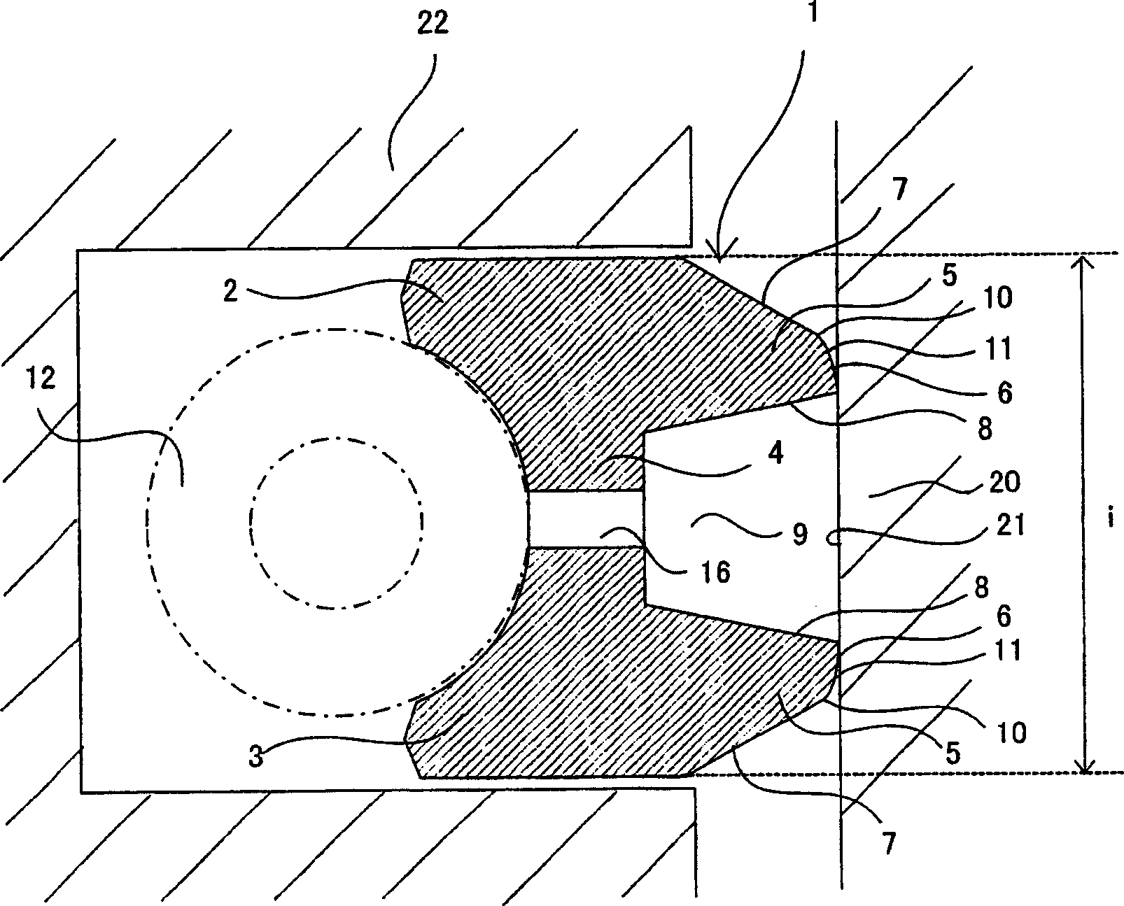
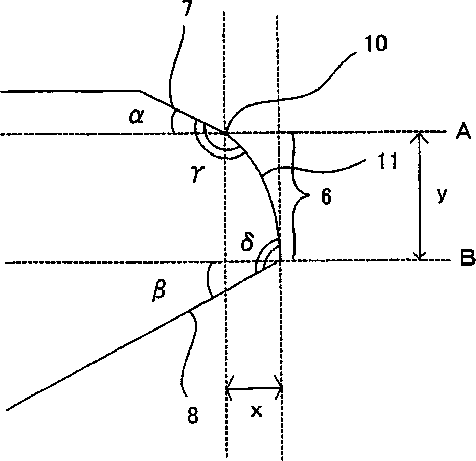
[0033] The first embodiment is an oil ring whose cross-section is slightly I-shaped by connecting two ring rails with a column. It is characterized in that the sliding part protrusions formed on the two ring rails have: The outer surface of the sliding part protrusion of the raised outer part, the inner surface of the sliding part protrusion forming the inner part of the above-mentioned sliding part protrusion, the sliding surface that slides with the inner wall of the cylinder and forms the front end part of the above-mentioned sliding part protrusion, the above-mentioned sliding part protrusion The inclination angle of the outer surface is in the range of 10° to 60°, the outer edge portion of the outer surface of the sliding part protrusion and the sliding surface joint is formed in a curved shape, and the sliding surface has a The outer surfaces are joined and formed as a curved sliding portion in the shape of a gentle slope curved surface.
[0034] In this embodiment, by f...
no. 2 example
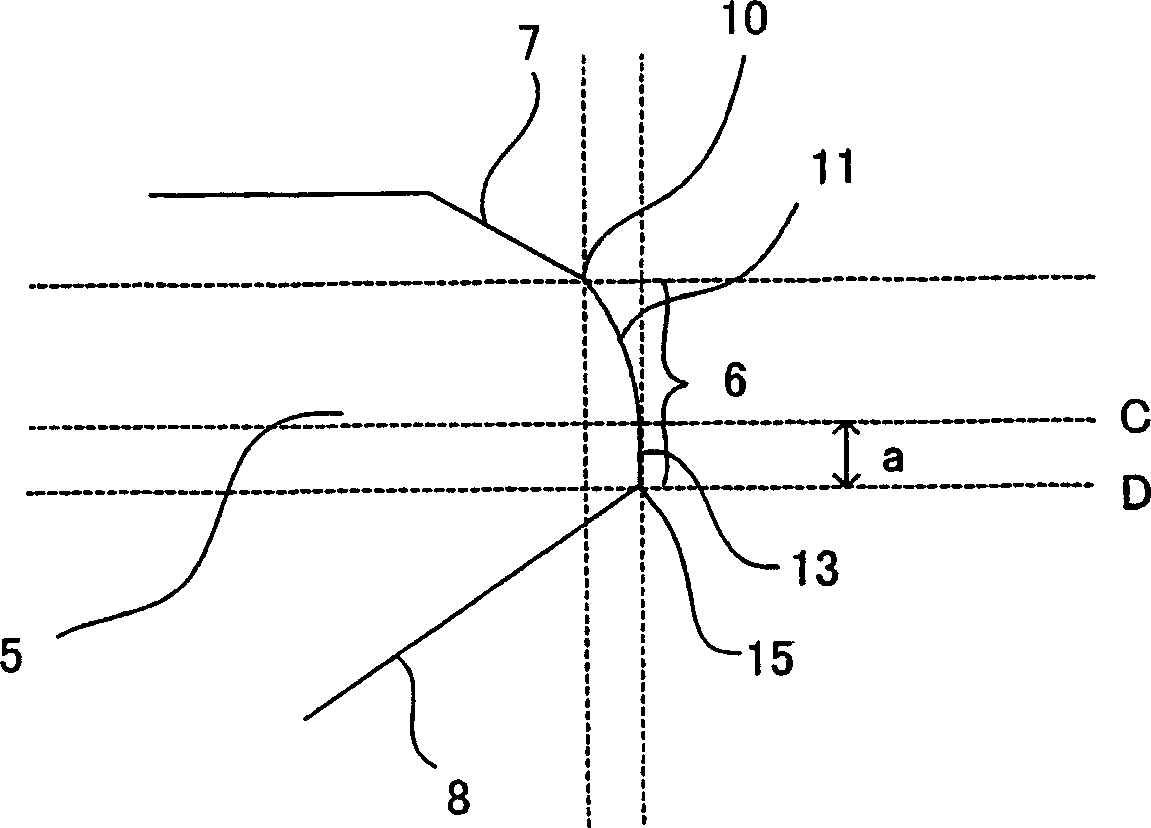
[0075] The second embodiment will be described below. In this embodiment, two ring rails are connected by a column, and the cross-section is roughly I-shaped. The sliding part protrusion formed by the above two ring rails has: The side surface, the inner side surface of the protrusion of the sliding part forming the inner part of the protrusion of the sliding part, and the sliding surface which slides with the inner wall of the cylinder and forms the front end part of the protrusion of the sliding part are characterized in that the outer surface of the protrusion of the sliding part is At least a part of the outer edge portion of the protrusion outer surface of the sliding portion joined to the sliding surface is formed in a curved shape, the outer edge portion is formed in a curved shape, and the sliding surface has a The side surfaces are joined and formed as a gently sloped curved surface sliding portion.
[0076] In this embodiment, as in the first embodiment, by providin...
Embodiment
[0082] The following examples are described to further illustrate the present invention.
[0083] [Unit test]
[0084] First, for the oil ring of the present invention, the frictional mechanical loss (FMEP) by a single test machine was obtained. The test method at this time is to install the oil ring on the piston, and after the running-in operation, change the number of revolutions equivalent to the engine speed at an oil temperature of 80°C, and measure the friction force.
[0085] The oil ring used in this example is made of Cr: 8.0wt%, C: 0.72wt%, Si: 0.25wt%, Mn: 0.28wt%, P: 0.02wt%, S: 0.01wt%, and others Wire rods for piston rings free from impurities. Wire drawing and well-known processing methods (grinding, etc.) are applied to this piston ring wire, and then gas nitriding treatment is performed on the surface to form a Hv700 or higher diffusion layer with a thickness of 100 μm. The adjustment of the amount of the roller is to use the angle of the installation tool...
PUM
 Abstract
Description
Claims
Application Information
 - R&D
- Intellectual Property
- Life Sciences
- Materials
- Tech Scout
- Unparalleled Data Quality
- Higher Quality Content
- 60% Fewer Hallucinations
Browse by: Latest US Patents, China's latest patents, Technical Efficacy Thesaurus, Application Domain, Technology Topic, Popular Technical Reports.
© 2025 PatSnap. All rights reserved.Legal|Privacy policy|Modern Slavery Act Transparency Statement|Sitemap|About US| Contact US: help@patsnap.com


