Shaft drive buffer mechanism

A buffer mechanism and shaft transmission technology, which is applied in the direction of couplings, mechanical equipment, elastic couplings, etc., can solve the problems of inconvenient installation and increased difficulty of manufacturing process

Active Publication Date: 2005-12-21
CHONGQING CHUANYU JINGGONG MACHINERY PARTS DEV
View PDF0 Cites 7 Cited by
  • Summary
  • Abstract
  • Description
  • Claims
  • Application Information

AI Technical Summary

Problems solved by technology

For the 100ml~200ml motorcycle engine, the installation position is small, which is inconvenient to install, and it also makes

Method used


Image

  • Shaft drive buffer mechanism
  • Shaft drive buffer mechanism

Examples


Embodiment Construction

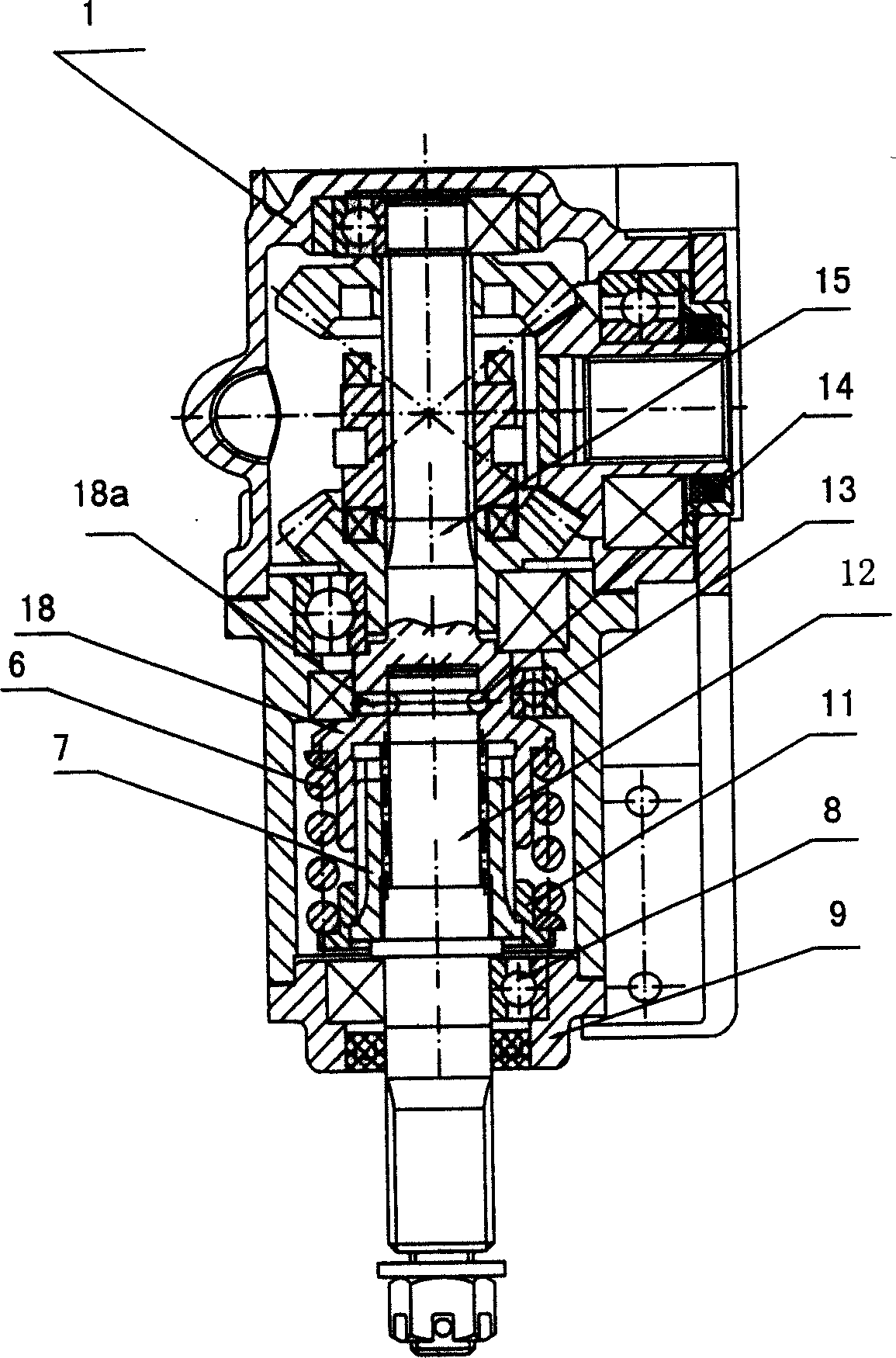
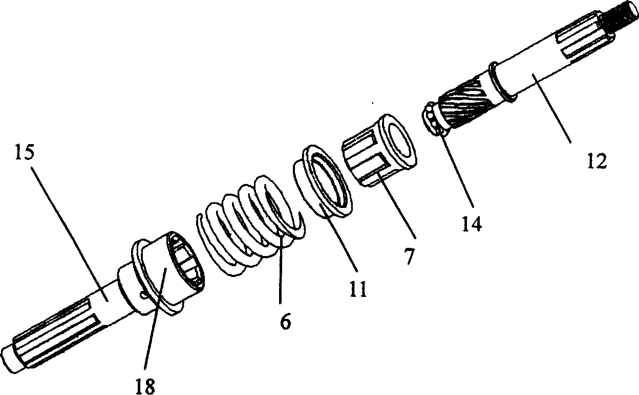
[0016] Referring to the above-mentioned drawings, a shaft transmission buffer mechanism is characterized in that: the power input shaft of the shaft transmission and the power output shaft 12 are splined through the spline sleeve 7 with the compression spring 6 outside, and the power output shaft 12 is splined. The front end is provided with an outer R groove, which matches the inner R groove of the power input shaft, and steel balls 14 are arranged in the inner and outer R grooves.

[0017] The above-mentioned power input shaft is a shaft sleeve 18, and the shaft sleeve 18 is connected with the outer garden of the spline sleeve 7 by a straight tooth spline, and the inner hole of the spline sleeve 7 and the power output shaft 12 are a helical tooth spline Connection; the above-mentioned shaft sleeve 18 has a steel ball installation hole 18a communicating with the inner R groove.

[0018] The present invention is specifically applied in the three-wheel motorcycle engine shaft t...


PUM


Abstract

This invention discloses one kind of drive shaft transmission cushion organization for use in engine, its characteristic lay in: The axis transmission power input axis and the power output shaft are connected by a spline with a pressure spring. The said power output shaft front end has the outside R trough, this outside R trough matches the R trough match in the power input shaft .In the inside and outside R trough is set with a steel ball.

Description

technical field [0001] The invention relates to a shaft transmission buffer mechanism, in particular to a shaft transmission buffer mechanism for motor vehicles, such as two-wheel, three-wheel, four-wheel motorcycles and beach vehicles. Background technique [0002] In the current shaft transmission device, the power input shaft and the power output shaft are usually directly assembled through a universal joint. This direct assembly structure is a hard transmission (that is, rigid transmission) during the power transmission process. It is the moment when the object accelerates, the impact on the power source of the shaft transmission device is quite large. Taking the engine shaft transmission of motor vehicles as an example, most of their engines adopt a structure in which the drive shaft passes through the rigid connection between the universal joint and the final drive of the rear axle. This rigid connection will change with the driving conditions of the vehicle, such as ...

Claims


Application Information

Patent Timeline
IPC IPC(8): F16D3/12
Inventor 付置贵高同大杨驰
Owner CHONGQING CHUANYU JINGGONG MACHINERY PARTS DEV
Why Eureka
Try Eureka