Mobile-terminal multi-antenna system

A multi-antenna system, mobile terminal technology, applied in the direction of the radiating element structure, etc., to achieve the effects of small correlation, small size, and large antenna gain

Inactive Publication Date: 2005-12-21
TSINGHUA UNIV
View PDF0 Cites 10 Cited by
  • Summary
  • Abstract
  • Description
  • Claims
  • Application Information

AI Technical Summary

Problems solved by technology

[0006] The purpose of the present invention is to provide a multi-antenna system for mobile terminals in order to overcome the disadvantages of using a single antenna performance in existing mobile communication equipment in a complex mobile propagation environment

Method used


Image

  • Mobile-terminal multi-antenna system
  • Mobile-terminal multi-antenna system
  • Mobile-terminal multi-antenna system

Examples


Embodiment Construction

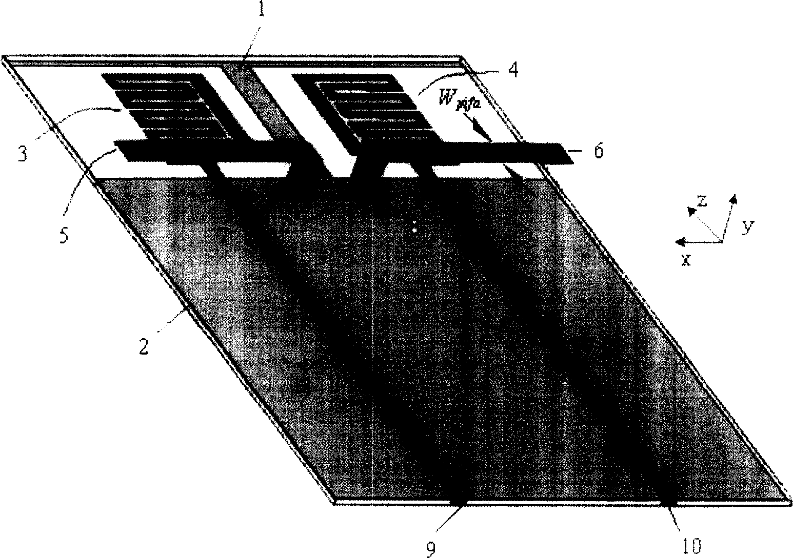
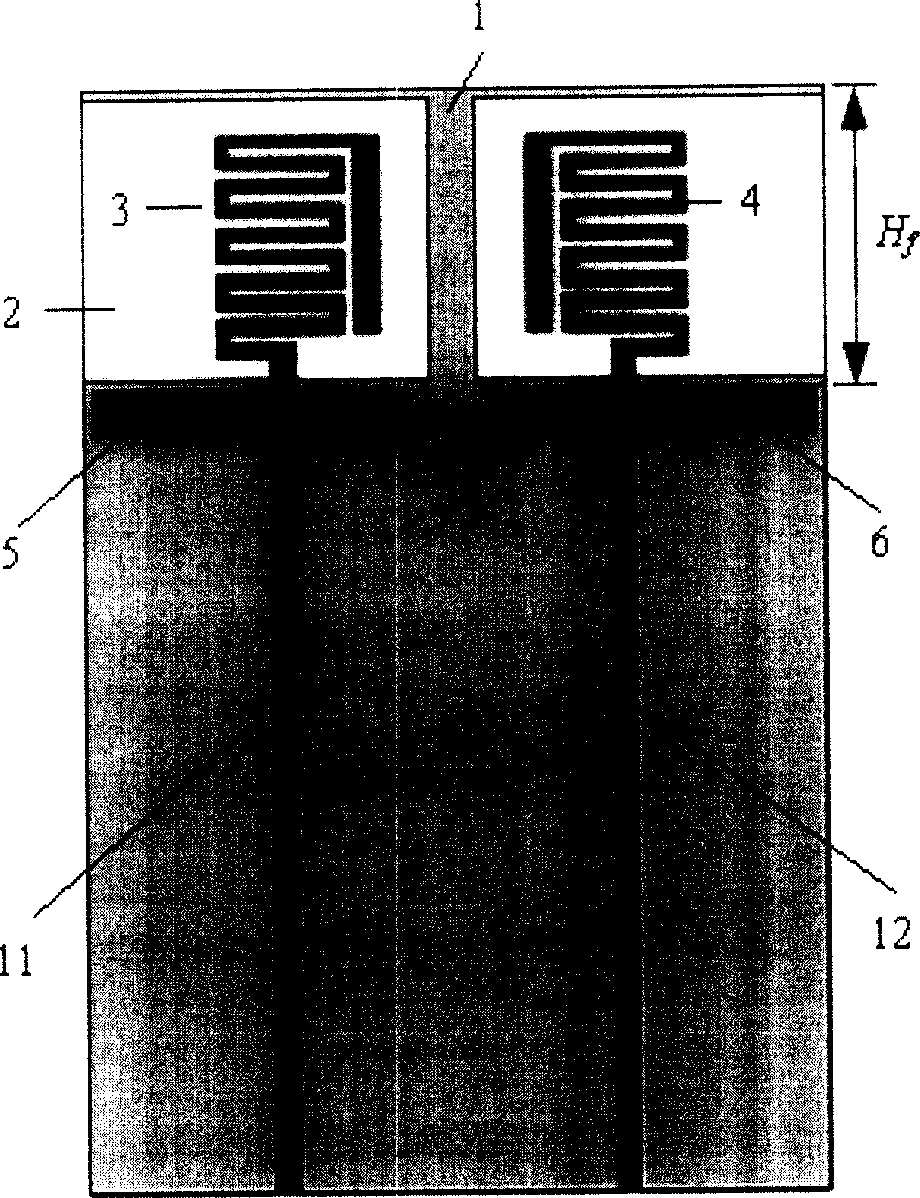
[0026] The present invention proposes a multi-antenna system composed of four antenna units, the structure schematic diagram is as follows figure 2 As shown, it includes two planar monopole antennas, two planar inverted F antennas (PIFA), a dielectric board and a T-shaped ground plane. figure 2 Among them, 1 is a T-shaped ground plane, 2 is a dielectric plate, 3 is the first planar monopole antenna, 4 is the second planar monopole antenna, 5 is the first planar inverted F antenna, and 6 is the second planar monopole antenna. A planar inverted F antenna, 7 is the feed point of 5, 8 is the feed point of 6, 9 is the feed point of 3, 10 is the feed point of 4, 11 is the feed microstrip of 3, 12 is the feed point of 4 The feeding microstrip, the total size of the four antennas is 68×30×6(mm 3 ), the connection relationship of each part is as follows: the T-shaped ground plane is made of copper foil printed on the lower surface of the rectangular dielectric board. The two planar...


PUM


Abstract

Multiaerial system is composed of two pieces of plane type monopole antenna and two pieces of plane type inversion F antenna. The inversion F antenna is perpendicular to the monopole antenna. Vertical distance between two pieces of feed line is 15mm. It is 4mm of distance between the feed point of inversion F antenna and central line at Z-axis direction of dielectric plate, where two pieces of monopole antenna and two pieces of plane type inversion F antenna are located at. It is 26mm of distance between upper edge of inversion F antenna and upper edge of T type ground plane. Position of plane type inversion F antenna on the said dielectric plate is located above plane type monopole antenna vertically. Radiating elements in two pieces of plane type inversion F antenna are near to ends of two sides of dielectric plate or folded to T type ground plane. Advantages are: small size, little relativity between antennae, large gain and according with requirement of mobile communication.

Description

technical field [0001] The invention belongs to the field of mobile terminal antenna design, in particular to a multi-antenna system structure design for a mobile terminal in a complex communication environment. Background technique [0002] The antenna is an important part of the communication system, and its performance has an important impact on the function of the entire communication system. In existing mobile communication terminals, one antenna is usually used as the transmitting and receiving antenna. The mobile communication system is continuously upgraded in terms of function, capacity, quality and service business, which puts forward higher and higher performance index requirements for mobile terminal antennas; at the same time, the antenna system usually works in a complex mobile propagation environment, and radio waves propagate in the air It will be fading in many ways, and the channel will be affected by environmental factors such as terrain, temperature, and...

Claims


Application Information

Patent Timeline
Patent Type & Authority Applications(China)
IPC IPC(8): H01Q1/38
Inventor 王非凡杜正伟王蔷龚克
Owner TSINGHUA UNIV
Why Eureka
Try Eureka