

Driving wheel for driving an auxiliary apparatus of a vehicle
A technology for auxiliary units and transmission wheels, which is applied in the direction of machines/engines, mechanical equipment, vehicle parts, etc., and can solve problems such as affecting vibration conditions
- Summary
- Abstract
- Description
- Claims
- Application Information
AI Technical Summary
Problems solved by technology
Method used
Image

Examples
Embodiment Construction
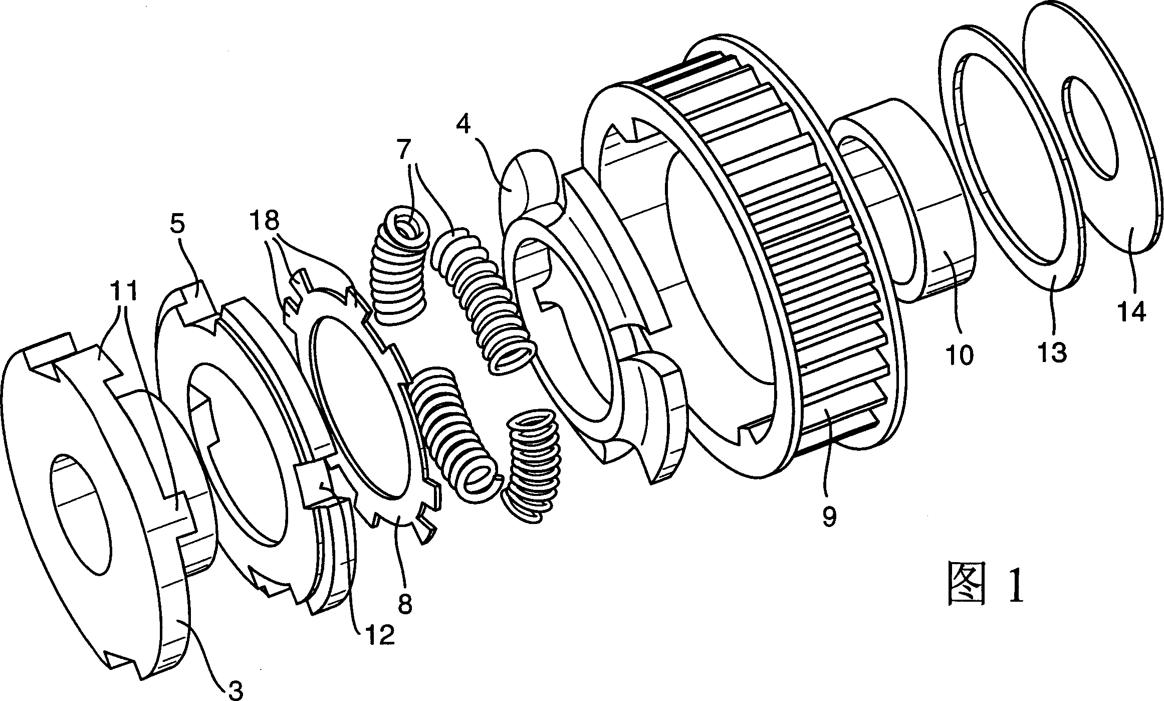
[0024] FIG. 1 shows a possible variant of the transmission wheel according to the invention and its individual components with the aid of an exploded view.
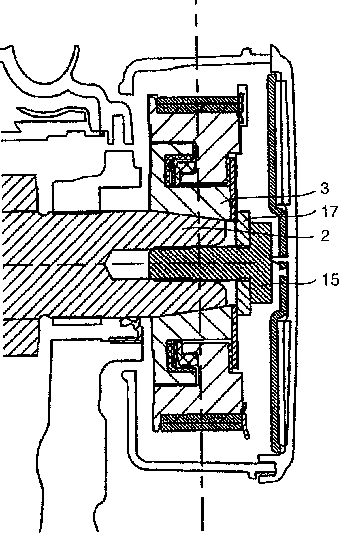
[0025] The transmission wheel 1 according to the invention for driving an auxiliary unit of a motor vehicle has a vibration damping device and is mechanically coupled to a shaft. According to a possible embodiment, the transmission wheel 1 can be coupled with a camshaft 2 as a drive shaft. In this embodiment, the drive wheel 1 can be used to drive a high pressure pump of a common rail diesel fuel injection system.
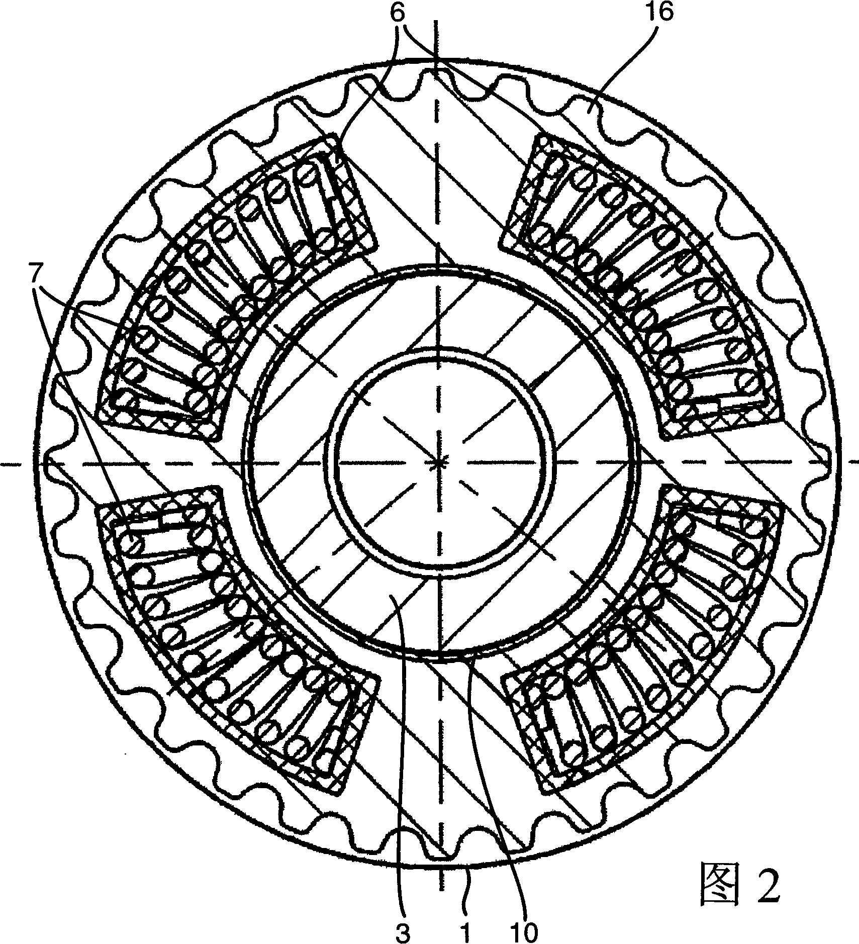
[0026] According to the invention, the damping device has a damper integrated in the transmission wheel 1, which is a torsional vibration damper that operates without lubricant. In this way, a considerable reduction in the transmission of vibrations between camshaft 2 and high-pressure pump can be achieved without additional or balancing masses.
[0027] The torsional vibration damper has a damper holder for...
PUM
 Abstract
Description
Claims
Application Information