Quantum minitype propeller using vacuum

A micro thruster and zero-point energy technology, applied in the direction of microstructure devices, relays, snap-action devices, etc., which are composed of components that move relative to each other, to achieve the effect of solving the problem of energy limitation

Inactive Publication Date: 2006-01-11
JIANGSU UNIV
View PDF0 Cites 4 Cited by
  • Summary
  • Abstract
  • Description
  • Claims
  • Application Information

AI Technical Summary

Problems solved by technology

At present, there are no reports or patent documents on the use of vacuum "zero-point energy" to realize the drive of quantum micro-thrusters

Method used


Image

  • Quantum minitype propeller using vacuum

Examples


Embodiment Construction

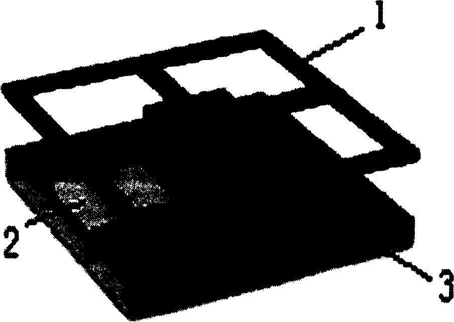
[0010] figure 1 The working process of the micro-propeller shown in is as follows: first, let the stopper 2 move horizontally to the right to block the microcavity above the base 3, so that the plane in the piston assembly 1 forms two parallel structures with the stopper 2, so that The Casimir force between the two is gravitational force, which attracts the piston assembly 1 to move downward, while the frame of the piston assembly 1 remains stationary, so that it just pulls the four cantilevers (equivalent to the function of springs) on it to follow the piston assembly The planes in the body 1 move downward together. When the plane in the piston assembly 1 moves to the bottom position, it can be considered that the elastic restoring force is equal to the Casimir force at this time, and the cantilever at this time has the largest elastic potential energy; 2. Move left horizontally, so that the piston 1 faces the microcavity on the base 3 to form a rectangular cavity structure. ...


PUM


Abstract

A miniature quantum propulsion using the zero point energy in vacuum is composed of a piston assemblage consisting of a peripheral frame, a central plane as piston and 4 beams as spring connected to said central plane, a base with a rectangular cavity, and a barrier plate for shielding said rectangular cavity.

Description

technical field [0001] The invention relates to a micro-propeller, in particular to a quantum micro-propeller driven by vacuum "zero-point energy". Background technique [0002] Micro-propulsion systems supported by MEMS technology have broad application prospects because of their higher power density, better mobility, and high reliability than large propulsion systems. The micro propulsion system can be used as a mobile power source, as a pocket power system for the power source of micro-surgical instruments in medical treatment, as a power source for cooling the human body, as an electronic component actuator, etc. It can also be used as a power source for thrust engines, such as micro-aircraft Thrusters etc. At the same time, because the micro-propulsion system has a very high thrust-to-weight ratio (an order of magnitude higher than that of ordinary aero-engines, up to 100:1, while the thrust-to-weight ratio of large engines is 10:1), and multiple micro-propulsions can ...

Claims


Application Information

Patent Timeline
Patent Type & Authority Applications(China)
IPC IPC(8): B81B5/00
Inventor 丁建宁朱国华杨继昌
Owner JIANGSU UNIV
Why Eureka
Try Eureka