Coaxial connector with a switch

A coaxial connector and switch technology, which is applied in the direction of connection, two-part connection device, and parts of the connection device, can solve the problems of high component cost and assembly cost, large number of components, complex structure, etc., so as to reduce the cost of components and assembly cost, good high frequency characteristics, the effect of simplified shape

Inactive Publication Date: 2006-01-11
HOSIDEN CORP
View PDF1 Cites 6 Cited by
  • Summary
  • Abstract
  • Description
  • Claims
  • Application Information

AI Technical Summary

Problems solved by technology

[0004] However, conventional coaxial connectors with switches have other components such as sub-boards and relay pins in addition to the four components of the insulating member, the outer conductor case, the fixed contact member and the movable contact member for the switch. , the sub-substrate has a solder connection portion for surface mounting to a printed circuit board, and the relay pin is used to electrically connect the fixed contact member and the movable contact member with respect to the solder connection portion of the sub-substrate, for this purpose, The number of components is large, the structure is complicated, and there are problems of high component cost and assembly cost
In addition, the pin contact portion of the movable contact piece member is formed in an L shape from the free side end of the movable contact piece member through the lower side of the pin insertion area, standing up on the side thereof, and as mated with the mating connector, The pin is in contact with the upright portion of the pin contact portion, and the entire pin contact portion moves in a direction substantially perpendicular to the plug insertion and withdrawal direction, so that the movable contact portion of the movable contact member is separated from the fixed contact portion against the spring force, Therefore, it is necessary to further ensure the plate thickness of the lateral portion of the plug contact portion and the sliding clearance of the lateral portion on the lower side of the plug insertion area, which is a structure that is disadvantageous for height reduction.

Method used


Image

  • Coaxial connector with a switch
  • Coaxial connector with a switch
  • Coaxial connector with a switch

Examples


Embodiment Construction

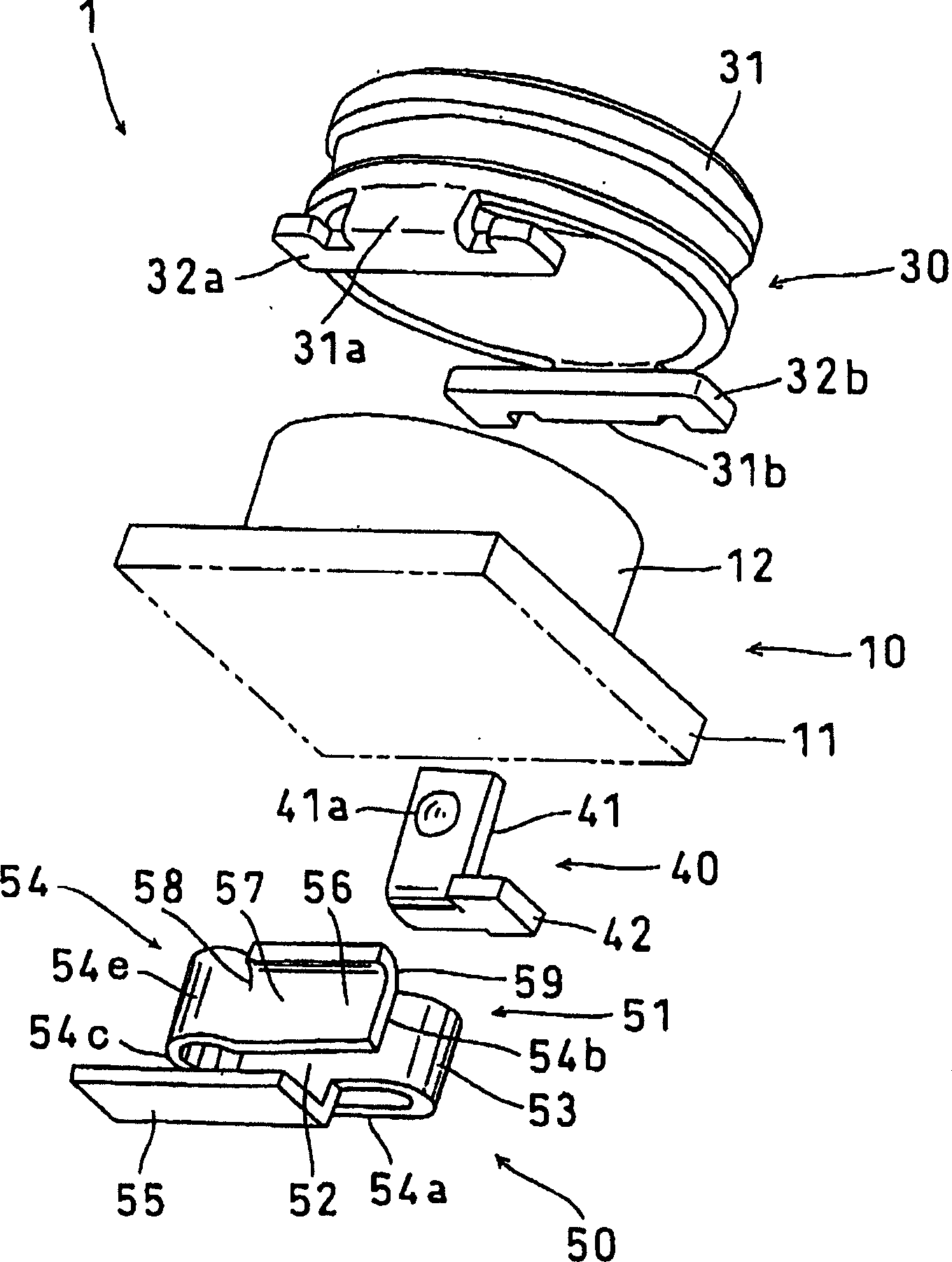
[0037] Below, refer to Figure 1 to Figure 10 A first embodiment of the present invention will be described. like figure 1 As shown, the coaxial connector 1 with a switch is constituted by only four parts of an insulating member 10 , an outer conductor case 30 , a fixed connection member 40 for switching, and a movable connection member 50 .

[0038] Next, each component will be described.

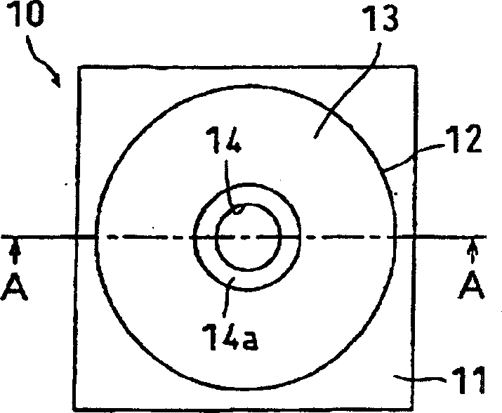
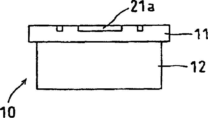
[0039] Insulation parts 10, such as figure 1 , as shown in FIG. 2 , is made of an insulating resin material (for example, LCP), and is formed into a cylindrical shape with a top integrally having a substantially rectangular parallelepiped pedestal 11 on the bottom side. The pedestal part 11 is formed in a square plate shape, and the length of one side is equal to the outer diameter dimension of the cylindrical insulating member main body 12 plus the thickness of the metal thin plate forming the outer conductor case 30, that is, the outer conductor case The outer diameter of the case bo...


PUM


Abstract

The invention provides a coaxial connector with a switch in which the life property and contact reliability of a movable contact piece portion are improved, which is further miniaturized and low-profiled than the conventional art, and in which the component configuration is simple, and hence the production cost is low. A coaxial connector 1 with a switch is configured by four components of an insulation body 10 having a pedestal portion 11, an external-conductor shell 30 having solder connecting portions, a stationary connect member 40, and a movable connect member 50. The movable connect member 50 has a plate-spring like movable contact piece portion 51 configured by a thin metal plate. The movable contact piece portion is housed in a cantilevered manner inside the body so that a plate width direction is in parallel with a direction of insertion and extraction of a plug pin. A free side end portion 54b laterally passes a part of a plug pin insertion region 15 to elongate to a stationary contact portion 41, and has a plug pin contact portion 57 in the same plane as a movable contact portion 56. In accordance with fitting with a counter connector, a plug pin 100 is elastically contacted with the plug pin contact portion, and the movable contact piece portion is displaced in a direction substantially perpendicular to the direction of insertion and extraction of the plug pin against the spring force, and separated from the stationary contact portion.

Description

technical field [0001] The present invention relates to a coaxial connector with a switch (socket with a switch), which is used in communication equipment such as electronic equipment such as mobile phones. Plug) to switch the contacts. Background technique [0002] The coaxial connector with switch can be installed on the surface of the substrate in the following way, that is, in the case of mobile phones, for example, the electrical characteristics of the high-frequency circuit should be checked when leaving the factory. Connect the high-frequency circuit from the antenna to the measurement device, and then connect the high-frequency circuit to the antenna again by removing the mating connector; in order to reduce the size and thickness of the target equipment such as mobile phones, it is desirable to realize as much as possible Miniaturization and low height. [0003] In order to realize the miniaturization and low height of the coaxial connector with switch, it is very...

Claims


Application Information

Patent Timeline
Patent Type & Authority Applications(China)
IPC IPC(8): H01R24/02H01R13/70H01R24/38
Inventor 长田孝之今井彻
Owner HOSIDEN CORP
Why Eureka
Try Eureka