
Surface light source device, illumination unit and light flux control member

A beam control, surface light source technology, applied in optical elements, optics, nonlinear optics, etc., can solve the problem of difficult to form planes in a continuous connection, and achieve the effect of ensuring uniformity

Active Publication Date: 2006-01-18
ENPLAS CORP
View PDF1 Cites 9 Cited by
  • Summary
  • Abstract
  • Description
  • Claims
  • Application Information

AI Technical Summary

Problems solved by technology

[0014] (2) Second Conventional Example: The plurality of concave lenses 105 of the light-emitting display device 103 are hardly said to be continuously connected to form a plane.
As a result, the lighting unit 1 cannot efficiently and smoothly spread the light from the LED 5 to a desired range.

Method used


Image

  • Surface light source device, illumination unit and light flux control member
  • Surface light source device, illumination unit and light flux control member
  • Surface light source device, illumination unit and light flux control member

Examples


Embodiment Construction

[0057] Embodiments of the present invention will be described below with reference to the drawings.

[0058] [Schematic configuration of surface light source device and lighting unit]

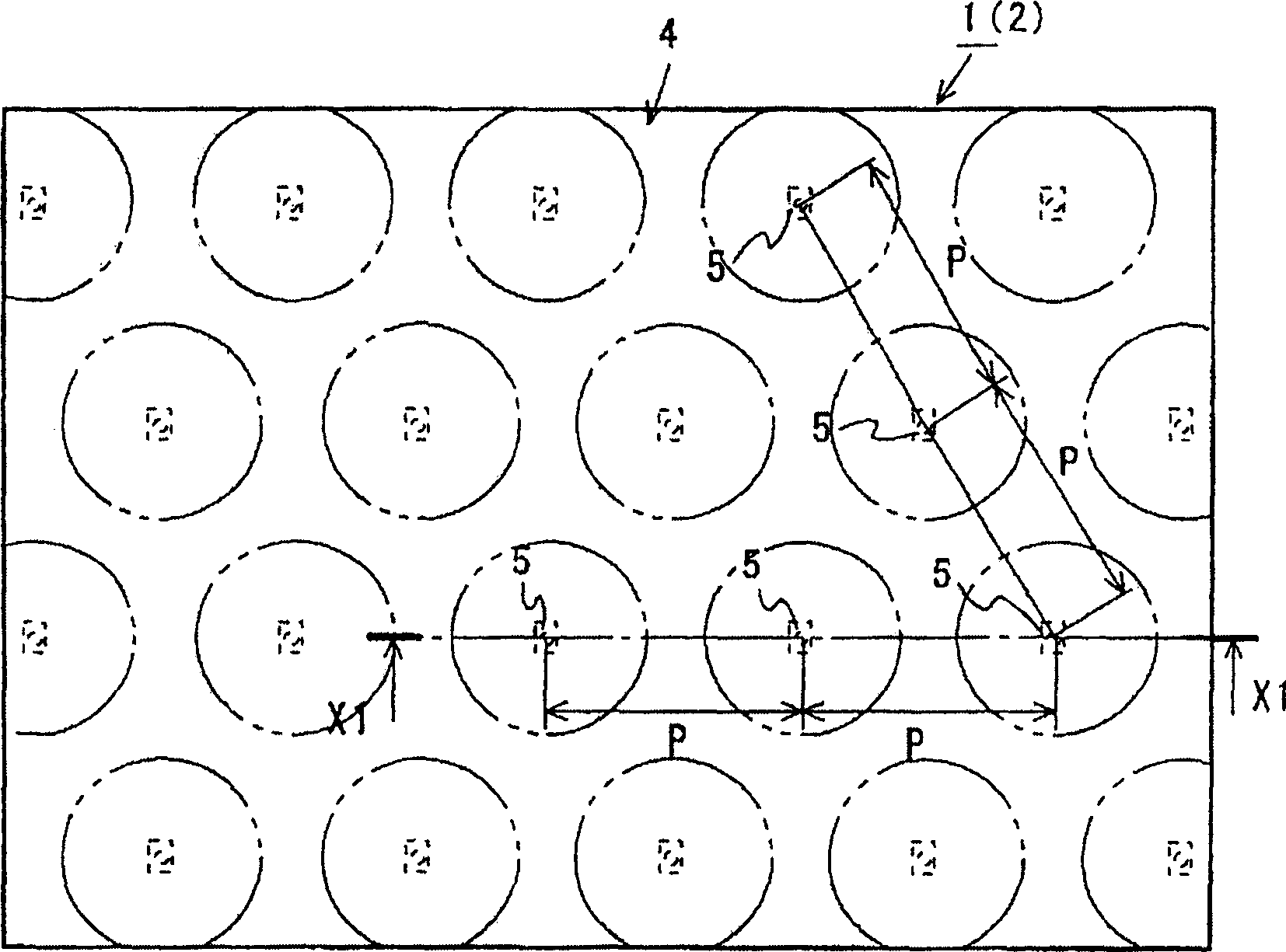
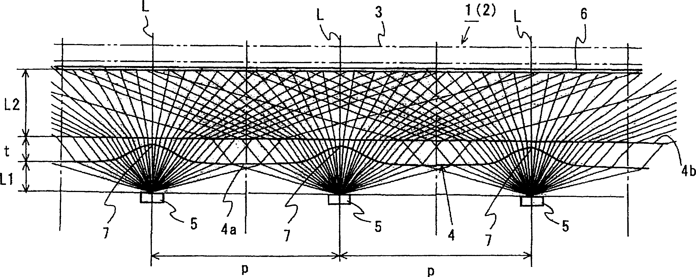
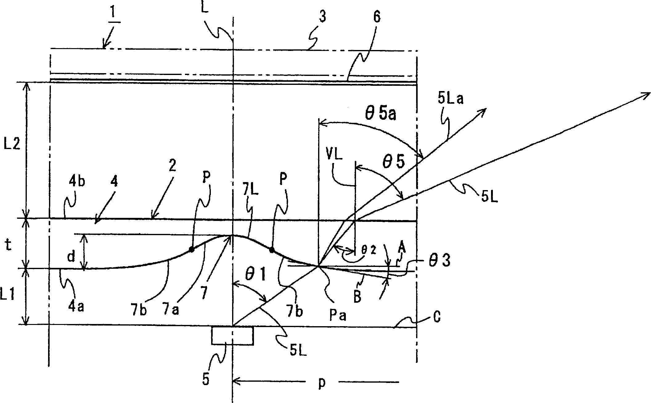
[0059] Figure 1 ~ Figure 3 The lighting unit 1 of the present embodiment and the surface light source device 2 included in the lighting unit 1 are shown. figure 1 It is a plan view (a plan view of a surface light source device) of the lighting unit 1 excluding an illuminated member (for example, a liquid crystal display panel) 3 and the like. in addition, figure 2 is along figure 1 The sectional view of the lighting unit 1 on the line X1-X1. in addition, image 3 It is a partial cross-sectional view of the lighting unit passing through the optical axis L of the LED 5, and it is shown enlarged in order to describe the shape of the concave portion 7 in detail. figure 2 a part of.

[0060] As shown in these figures, the lighting unit 1 includes: a light flux control member 4; a plurali...


PUM


Abstract

Light flux control member 4 receives light from at least one LED 5, letting the light be emitted from emission face 4b. Light flux control member 4 is provided with recess 7 corresponding to each LED 5. Each recess 7 is configured so as to satisfy the following Conditions 1 and 2 for at least light which is emitted toward within a half-intensity-angular-range from corresponding LED 5. Condition 1: Relation 5 / 1>1 is satisfied except for light emitted toward within an angular-neighbourhood of a normal direction with respect to emission face 4b; Condition 2: Value of 5 / 1 decreases gradually according to increasing of 1; If a plurality of LEDs are employed, differences in emitting color among individual LEDs are made less conspicuous and uniform illumination free from uneven brightness is realizable.

Description

technical field [0001] The present invention relates to a surface light source device, a lighting unit and a light beam control member, which are applicable to, for example, a surface light source device used for backlighting a liquid crystal display panel, a lighting unit using the surface light source device as an illumination mechanism, and a surface light source device used on these surfaces. On the light beam control member used on the light source device or lighting unit. More specifically, the surface light source device, lighting unit, and light flux control member of the present invention can be employed for backlighting of a television monitor or a monitor of a computer. In addition, it can also be widely used for indoor indicator lights, various lighting, and the like. Background technique [0002] Conventionally, a surface light source device using a plurality of light emitting diodes (LEDs) as point light sources has been known as an illumination mechanism for ...

Claims


Application Information

Patent Timeline
Patent Type & Authority Applications(China)
IPC IPC(8): G02F1/1335G02F1/13357
CPCG02F1/133611G02B3/0056G02F1/133603G02B3/0031G02F1/1335
Inventor 大川真吾
Owner ENPLAS CORP
Learn More