Sheet material identification apparatus and image forming apparatus therewith

A material identification and imaging device technology, applied in printing devices, printing, office printing equipment, etc.

Inactive Publication Date: 2006-02-01
CANON KK
View PDF5 Cites 15 Cited by
  • Summary
  • Abstract
  • Description
  • Claims
  • Application Information

AI Technical Summary

Problems solved by technology

In this type of device, the change in the fixing performance due to the change in heat capacity is more important than the difference cau

Method used


Image

  • Sheet material identification apparatus and image forming apparatus therewith
  • Sheet material identification apparatus and image forming apparatus therewith
  • Sheet material identification apparatus and image forming apparatus therewith

Examples


Embodiment 1

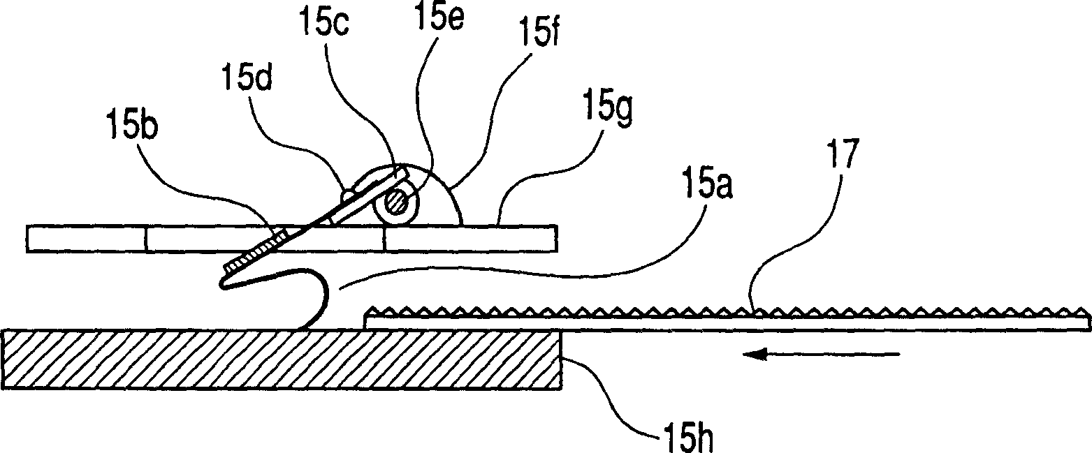
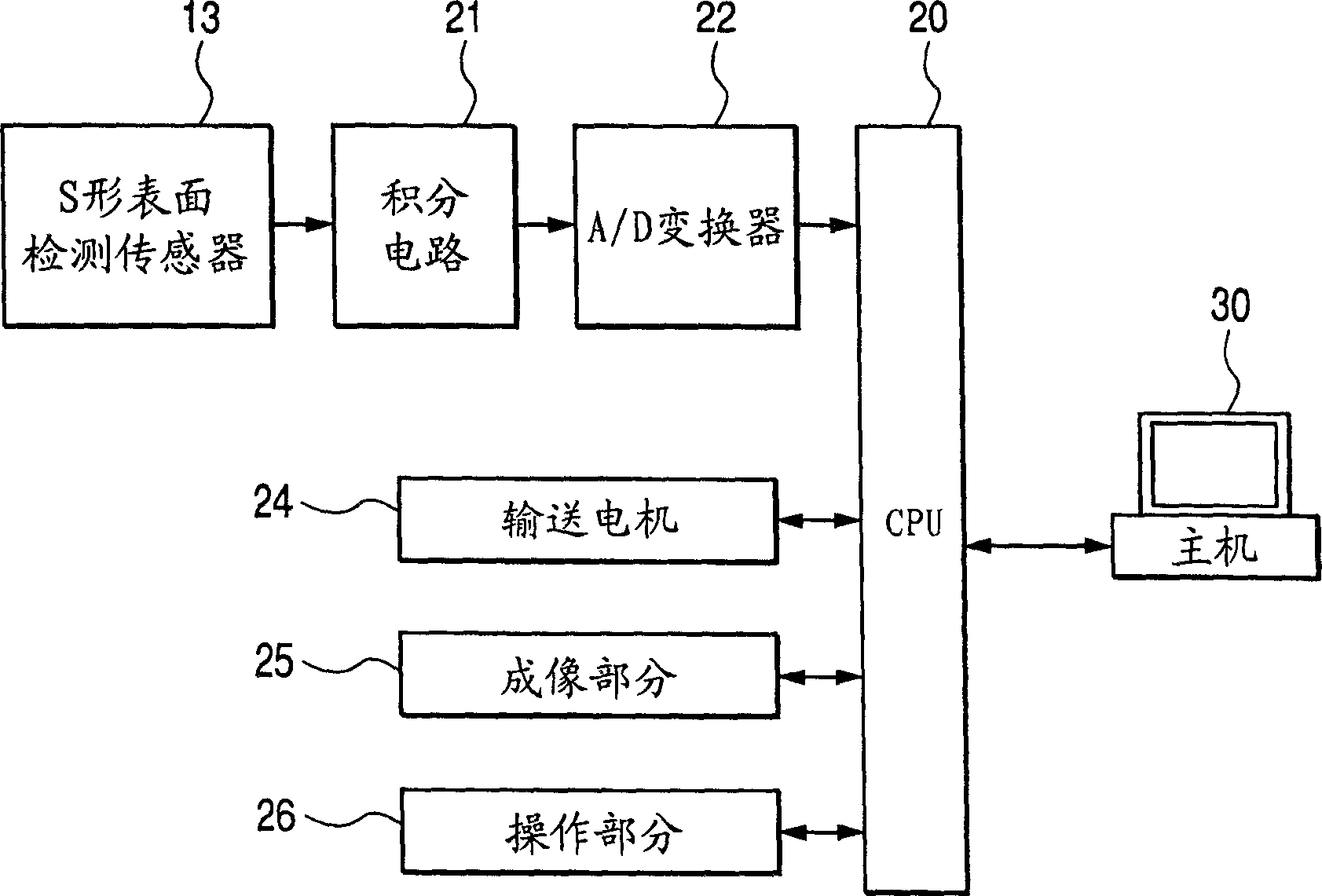
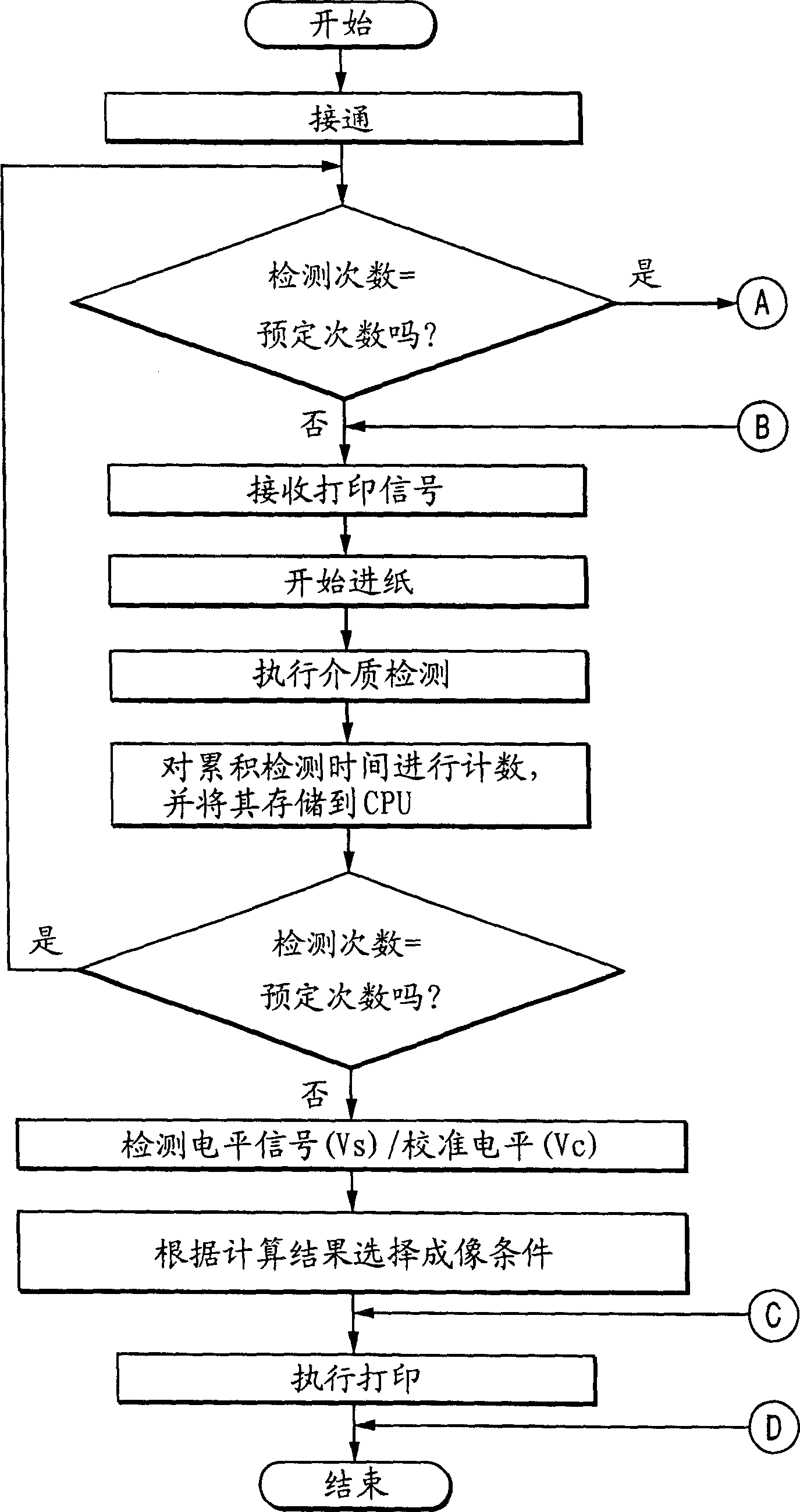
[0090] Figures 1 to 5 They are the sectional view, control block diagram, flow chart, corrected durability result, and sectional view of the calibrated sheet storage unit of the sheet material identification device according to Embodiment 1 of the present invention. here, in figure 1 , the same reference numerals are used for the Figure 7A corresponding components.

[0091] In this example, if figure 1 As shown, a calibration sheet 17 whose surface has been roughened to simulate a rough paper is conveyed to a sheet conveying plane portion 15a in contact with a probe tip portion of an S-shaped surface detection sensor 15, so that the sheet is detected according to the sensor. signal level to calibrate the sensor.

[0092] Regarding the main dimensions of each of the configuration parts above, the width of the probe is 4mm, the size of the opening in which the probe moves up and down is 6mm x 6mm, the length of the flat portion of the probe is 15mm, and the dimensions of...

Embodiment 2

[0101] Figure 10 11 and 11 are respectively a sectional view and a flow chart of the sheet material identification device according to Embodiment 2 of the present invention. here, in Figure 10 in, with figure 1 Corresponding elements are provided with the same reference numerals.

[0102] In this example, if Figure 10 As shown, the difference is that the double-sided foil calibration foil 17' has two sides, that is, one side is roughened on one side of the foil to resemble rough paper, and the other is smooth on the opposite side. The smoothness of the paper. This calibration sheet 17' is conveyed to the sheet conveying plane portion 15a in contact with the probe tip portion of the S-shaped surface detecting sensor 15 each time with the front side once and the back side once in total, so that each paper is detected according to the sensor. The sensor is calibrated based on the signal level behind the surface, and the main dimensions of the configuration components and...

Embodiment 3

[0106] Figure 12A , 12B and 12C are explanatory diagrams of a method of mounting a print cartridge in an electrophotographic system, an explanatory diagram of a calibration sheet setting method, and an explanatory diagram of a cartridge replacement method, respectively, relating to Embodiment 3 of the present invention.

[0107] In this embodiment, as shown in Fig. 12, conventionally, a cartridge 11' having an alignment sheet 17 mounted on the top surface of the cartridge is used as the above-mentioned periodical correction guide. When the printer main body 18 is used for the first time, the top cover 18a is opened in the direction of the arrow, and then the cartridge 11' with the calibration sheet is installed. The printer is configured so that the printer is unusable until a signal from the printer main body requesting calibration using the calibration sheet belonging to the cartridge is notified to the printer main body display portion or the host computer side. And, if ...


PUM

PropertyMeasurementUnit
The average particle sizeaaaaaaaaaa
Thicknessaaaaaaaaaa

Abstract

The sheet material identification apparatus, includes a sensor adapted to bring a probe having a built-in piezoelectric element into contact with a surface of sheet material being conveyed, and thereby to generate electric detection signals corresponding with irregularities of the sheet material surface; an identification part adapted to identify types of sheet material based on detection signals outputted from the above described sensor; and a correct part adapted to correct fluctuations in detection features of the above described sensor based on detection output of the above described sensor at the time when the above described sensor has detected correction sheet material having a predetermined surface roughness. The appratus prevents misdetection during use for a long period of sheet material identification apparatus that does not require any type-of-paper selection setting operation by a user and can implement good heat treating, fixing and image forming efficiently even if sheets of paper having various kinds of surface roughness.

Description

technical field [0001] The present invention relates to a sheet material identifying device for identifying a difference in surface frictional resistance of an object to be measured, and identifying a difference in surface roughness and a difference in surface material causing the difference, and a heating device and an imaging device equipped with the same Devices, for example, printers in electrophotographic systems, photocopiers, inkjet printers, thermal head printers, dot impact printers, facsimile machines, composite devices including these devices, and the like. Background technique [0002] Conventionally, any type of image forming apparatus is generally an apparatus for forming an image on sheet-like recording materials such as postcards of plain paper, cardboard, letter paper, and plastic-based film flat sheets for OHP, all of which employ a printer of an electrophotographic system , photocopiers, and facsimile machines as representative examples of such devices, a ...

Claims


Application Information

Patent Timeline
IPC IPC(8): B41L39/06B41L39/14B41J29/38
Inventor 竹田正美
Owner CANON KK
Why Eureka
Try Eureka