
Magnetostrictive device and its usage method, actuator, sensor

A magnetostrictive and drive technology, applied in the direction of magnetostrictive sensors, magnetostrictive devices, sensors, etc., can solve the problems of measurement accuracy impact, cost increase of stretch sensors, etc., to reduce displacement, improve measurement accuracy, and improve linearity Effect

Inactive Publication Date: 2006-02-01
TDK CORPARATION
View PDF4 Cites 5 Cited by
  • Summary
  • Abstract
  • Description
  • Claims
  • Application Information

AI Technical Summary

Problems solved by technology

[0011] Also, the technology disclosed in JP-A-2003-156382 concerning sensors is an effective technology for suppressing hysteresis characteristics of inductance, but it is necessary to additionally provide a power supply for supplying a pulse-like current and a current supply control circuit. Leading to an increase in the cost of the magnetostrictive sensor
In addition, since the pulsed current is supplied, heat generation of the second coil is unavoidable, and this heat generation will have a bad influence on the measurement accuracy.

Method used


Image

  • Magnetostrictive device and its usage method, actuator, sensor
  • Magnetostrictive device and its usage method, actuator, sensor
  • Magnetostrictive device and its usage method, actuator, sensor

Examples


Embodiment 1

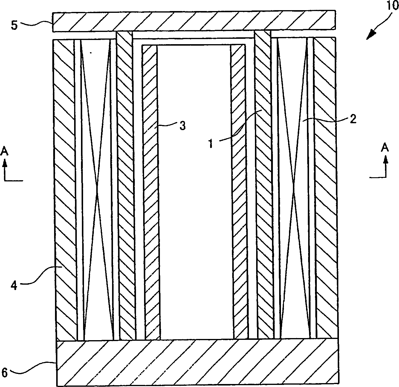
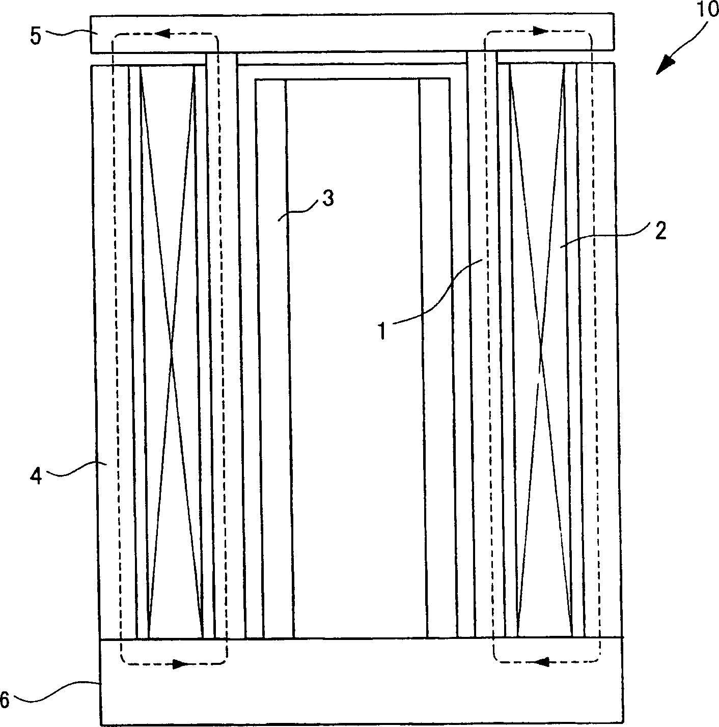
[0073] As the material of the magnetostrictive element 1, PMT-1 (trade name) manufactured by TDK Co., Ltd. was used, and as the material of the polar anisotropic cylindrical magnet 3, NEOREC 42H (trade name) manufactured by TDK Co., Ltd. was used. , make a driver (driver of the present invention) having the same structure as the driver 10. And, PMT-1 is with Tb 0.34 Dy 0.666 Fe 1.8 A giant magnetostrictive material composed of a sintered body. Furthermore, NEOREC 42H is a Nd-Fe-B based sintered magnet having the characteristics of a coercive force (HcJ) of 1500kA / m and a residual magnetic flux density (Br) of 1350mT.

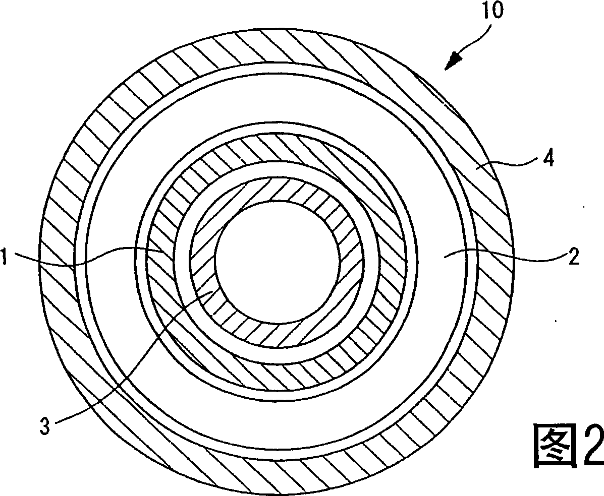
[0074] Furthermore, the magnetostrictive element 1 has dimensions of an outer diameter of 6 mm, an inner diameter of 4 mm, and a length of 20 mm, and the polar anisotropic cylindrical magnet 3 has dimensions of an outer diameter of 3.8 mm, an inner diameter of 2 mm, and a length of 18 mm.

[0075] In addition, as a comparison, an actuator (comparative actuat...

Embodiment 2

[0082] As the material of the magnetostrictive element 31, PMT-1 (trade name) manufactured by TDK Co., Ltd. was used, and as the material of the polar anisotropic cylindrical magnet 33, NEOREC 42H (trade name) manufactured by TDK Co., Ltd. was used. A magnetostrictive sensor having the same structure as the magnetostrictive sensor 30 (magnetostrictive sensor of the present invention) was produced. And, PMT-1 is with Tb 0.34 Dy 0.66 Fe 1.8 A giant magnetostrictive material composed of a sintered body. Furthermore, NEOREC 42H is a Nd-Fe-B based sintered magnet having the characteristics of a coercive force (HcJ) of 1500kA / m and a residual magnetic flux density (Br) of 1350mT.

[0083] Furthermore, the magnetostrictive element 1 has dimensions of an outer diameter of 6 mm, an inner diameter of 4 mm, and a length of 8 mm, and the polar anisotropic cylindrical magnet 33 has dimensions of an outer diameter of 3.8 mm, an inner diameter of 2 mm, and a length of 7 mm.

[0084] In a...


PUM

PropertyMeasurementUnit
Lengthaaaaaaaaaa
Coercivityaaaaaaaaaa

Abstract

Magnetostrictive devices, such as an actuator and a sensor, having a reduced hysteresis characteristic are provided. An actuator 10 includes a cylindrical magnetostrictive element 1 expanding or contracting in the axial direction by application of a driving magnetic field; an electromagnetic coil 2 placed on the outer surface side of the magnetostrictive element 1 and for applying the driving magnetic field; and a polar-anisotropic cylindrical magnet 3 placed on the inner surface side of the magnetostrictive element 1 and for applying a magnetic field to the magnetostrictive element 1. The polar-anisotropic cylindrical magnet 3 applies a magnetic field in the peripheral direction of the magnetostrictive element 1. The magnetic field orthogonally crosses the driving magnetic field applied to the magnetostrictive element 1 by the electromagnetic coil 2.

Description

technical field [0001] The present invention relates to a device using a magnetostrictive element, such as a driver, a vibrator, and a sensor, and particularly relates to a magnetostrictive device with reduced displacement hysteresis or inductance hysteresis. technical background [0002] When a ferromagnetic body is magnetized, the phenomenon that the size of the ferromagnetic body changes is called magnetostriction, and the material that produces this phenomenon is called a magnetostrictive material. The saturation magnetostriction coefficient, which is the saturation variation of magnetostriction, generally has 10 -5 ~10 -6 Magnetostrictive materials with a large saturation magnetostriction coefficient are also called giant magnetostrictive materials, and are widely used in drivers, vibrators, filters (filter), sensors, etc. For example, JP-A-10-84596 discloses a magnetostrictive device that reduces the number of coils and simplifies the structure. The magnetostrictive...

Claims


Application Information

Patent Timeline
IPC IPC(8): H01L41/12H04R15/00G01L1/12
Inventor 森辉夫
Owner TDK CORPARATION
Learn More