Optical device

A technology of optical devices and filters, which is applied in the direction of coupling of optical waveguides to reduce interference effects and improve reliability.

Inactive Publication Date: 2006-02-01
NGK INSULATORS LTD
View PDF1 Cites 7 Cited by
  • Summary
  • Abstract
  • Description
  • Claims
  • Application Information

AI Technical Summary

Problems solved by technology

In addition, when light is divided by the filter member 206 inserted into the slit 204 formed obliquely with respect to the optical axis direction, there is a characteristic of the reflected light 216 from the filter member 206 that is easily affected by the One and the problem of the interference of the reflected light 226, 228 and 230 of the second interface 220 and 224 etc.

Method used


Image

  • Optical device
  • Optical device
  • Optical device

Examples


Embodiment Construction

[0048] Below, refer to Figure 1-Figure 17 An embodiment in which the optical device of the present invention is applied to, for example, a 4-channel in-line power monitoring module will be described.

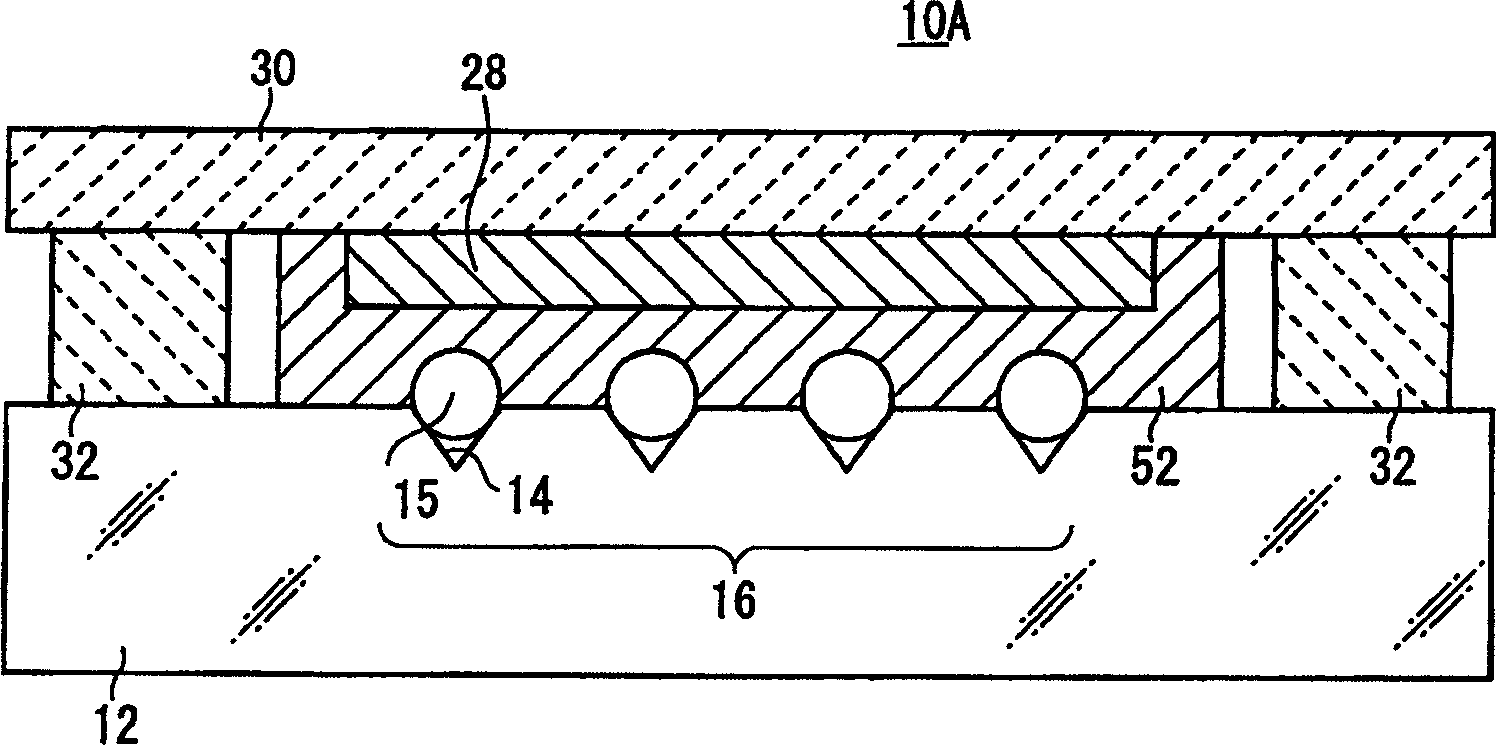
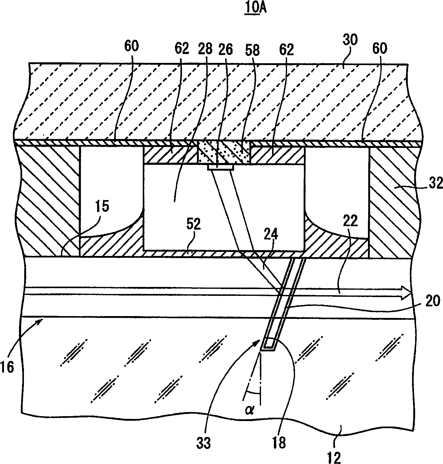
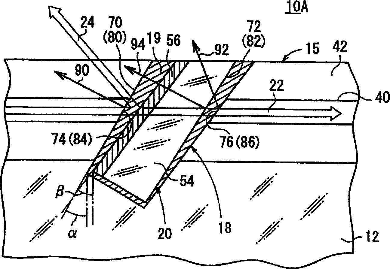
[0049] The optical device 10A of the first embodiment, such as figure 1 and figure 2 As shown, there is: a glass substrate 12, an optical fiber array 16 composed of a plurality of optical fibers 15 fixed in a plurality of V-shaped grooves 14 arranged on the glass substrate 12, extending from the upper surface of each optical fiber 15 to The slit 18 provided in the glass substrate 12 (refer to figure 2 ), the spectroscopic component (filter component) 20 inserted into the slit 18 (see figure 2 ), a PD (photodiode) array 28 of a plurality of active layers 26 for detecting at least light (reflected light) reflected by the filter member 20 etc. among the signal light 22 transmitted by each optical fiber 15 is arranged for mounting The PD array 28 is fixed toward the auxilia...


PUM


Abstract

The present invention provides an optical device, wherein when the multi-layer film (56) side surface of a filter member (20) is defined as a first surface (70) and the quartz substrate (54) side surface thereof is defined as a second surface (72), and the inner wall surface of a slit (18) opposed to the first surface (70) of the filter member (20) is defined as a first inner wall surface (74) and the inner wall surface thereof opposed to the second surface (72) of the filter member (20) is defined as a second inner wall surface (76), one or more of the first inner wall surface (74) and the second inner wall surface (76) of the slit (18) and the second surface (72) of the filter member (20) are positioned non-parallel with the first surface (70) of the filter member (20).

Description

technical field [0001] The present invention relates to optical devices having one or more optical fiber arrays or optical devices having one or more optical waveguides, and more particularly to optical devices suitable for en route monitoring of signal light transmitted through such optical transmission mechanisms. Background technique [0002] In the existing optical communication technology, the monitoring technology of communication quality is very important. Among them, the monitoring of optical output plays an important role in the field of wavelength multiplex communication technology (wavelength multiplex communication technology). [0003] In recent years, there have been increasing demands for miniaturization, high performance, and low cost of such optical output monitoring technology. [0004] Conventionally, for example, a technique disclosed in Japanese Patent Application Laid-Open No. 2001-264594 has been proposed. The technology such as Figure 18 As shown, ...

Claims


Application Information

Patent Timeline
Patent Type & Authority Applications(China)
IPC IPC(8): G02B6/42
Inventor 福山畅嗣岩崎康范井出晃启
Owner NGK INSULATORS LTD
Why Eureka
Try Eureka