Receiver tank for refrigeration cycle, heat exchanger with the receiver tank, and condensation device for refrigeration cycle

A refrigeration cycle and heat exchanger technology, applied in heat exchange equipment, evaporator/condenser, refrigerator, etc., can solve the problems of complex structure, increased cost, and high flow rate of refrigerant, and achieve simplified structure and reduced The effect of the number of parts

Active Publication Date: 2006-02-08
MAHLE INT GMBH
View PDF2 Cites 14 Cited by
  • Summary
  • Abstract
  • Description
  • Claims
  • Application Information

AI Technical Summary

Problems solved by technology

[0009] However, for a general refrigeration cycle, the flow rate of refrigerant flowing from the side of the condenser (CD) to the storage tank (RT) is high, so in Figure 14A ~ Figure 14C In the interlayer type shown, a large turbulent region of the liquid refrigerant occurs in the upper side space (133) into which the refrigerant flows, and as a result of this, the liquid refrigerant accumulates in the upper side space (133) , so the liquid refrigerant cannot be sufficiently supplied to the lower side space (134); or the tiny remaining liquid in the lower side space (134) is disturbed by the high-speed liquid flow through the desiccant filling layer (132), and gas refrigeration is generated at the same time Due to large-scale liquid level fluctuations, gaseous refrigerant flows out from the refrigerant outlet (137) exposed in the gas phase; or a large number of bubbles are involved in the exported liquid refrigerant, which is related to load fluctuations. The stability of performance deteriorates, the above-mentioned stable range bec

Method used


Image

  • Receiver tank for refrigeration cycle, heat exchanger with the receiver tank, and condensation device for refrigeration cycle
  • Receiver tank for refrigeration cycle, heat exchanger with the receiver tank, and condensation device for refrigeration cycle
  • Receiver tank for refrigeration cycle, heat exchanger with the receiver tank, and condensation device for refrigeration cycle

Examples


Embodiment Construction

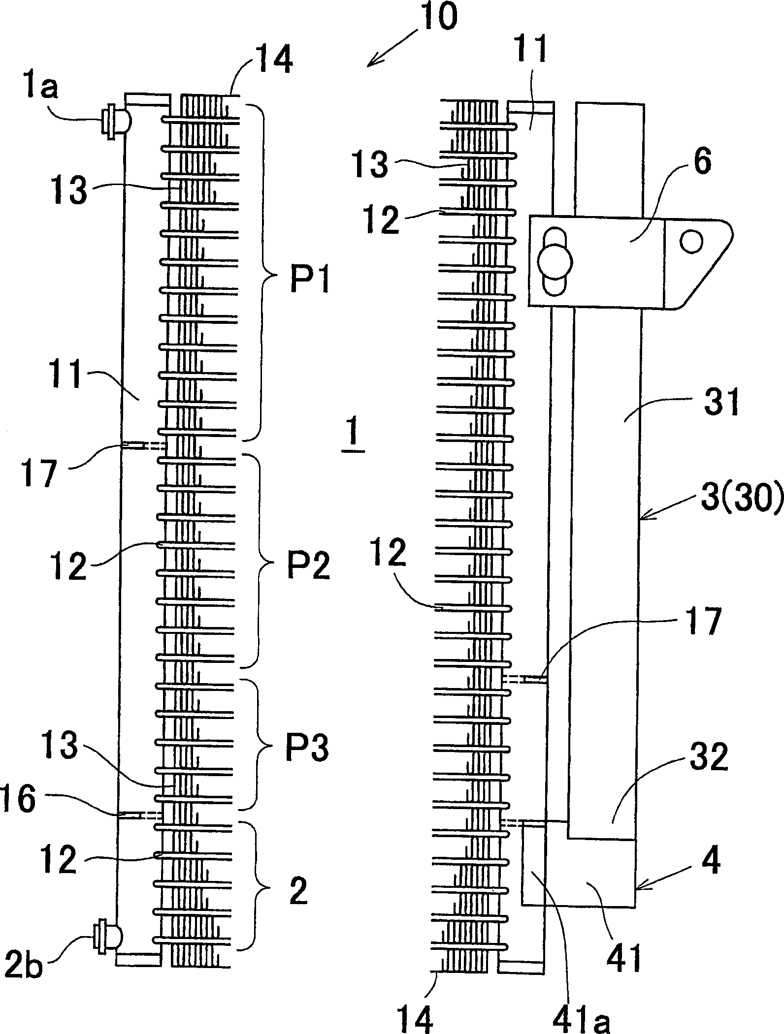
[0125] figure 1 It is a front view showing both side parts of the heat exchanger with storage tank which concerns on this embodiment of this invention. As shown in the figure, the heat exchanger is equipped with: a multi-channel type heat exchanger body (10), a storage tank (3), and a Block flange (4) for joining parts.

[0126] The heat exchanger body (10) is provided with a pair of header pipes (11) along the vertical direction opposite to each other with a certain interval. Between the pair of headers (11), a plurality of flat tubes (12) along the horizontal direction as heat exchange tubes are spaced vertically and vertically in a state where their respective ends are communicated with the two headers. arranged side by side at intervals. Furthermore, corrugated fins (13) are arranged between the flat tubes (12) and outside the outermost flat tube (12), and side plates are arranged outside the outermost corrugated fins (13). (14).

[0127] On the predetermined height ...


PUM


Abstract

A receiver tank has a tubular tank body (30) with a refrigerant inlet hole (3a) and a refrigerant outlet hole (3b) that are formed in its lower wall (321). The upper end of the opening of the refrigerant inlet hole (3a) is positioned lower than the upper end of the opening of the refrigerant outlet hole (3b). At the upper end of the opening of the refrigerant inlet hole (3a) is provided a resistance layer (335) at which the speed of flow of a refrigerant is reduced by permeation of the refrigerant. The refrigerant flowing in from the refrigerant inlet hole (3a) permeates upward the resistance layer (335) to form a collection (R) of liquid in a space in the tank. A liquid refrigerant in the collection (R) is discharged through the refrigerant outlet hole (3b). Because of the structure above, the refrigerant can be saved, the structure can be simplified, and costs can be reduced.

Description

technical field [0001] The present invention relates to storage tanks for refrigerating cycles, heat exchangers with storage tanks, and condensing devices for refrigerating cycles, which are suitable for use in automobiles, households, and commercial air-conditioning systems. Background technique [0002] In the refrigeration cycle of the expansion valve system, which is one of the representative systems of the refrigeration cycle, such as Figure 13 As shown, the high-temperature and high-pressure gas refrigerant ejected from the compressor (CP) enters the condenser (CD), exchanges heat with the outside air, and then cools, condenses and liquefies, and mainly flows into the storage tank (RT) in a liquid phase state to carry out After complete gas-liquid separation, only the liquid refrigerant is exported, and after being decompressed and expanded rapidly through the expansion valve, it is introduced into the evaporator (EP) in the form of low-pressure and low-temperature mis...

Claims


Application Information

Patent Timeline
IPC IPC(8): F25B39/04F25B43/00B60H1/32F25B41/00F28F9/04
CPCF25B39/04F25B2339/0446F28F9/0256F28F9/0246F25B2500/17F28F9/0253F25B41/00F25B2339/0441F25B2500/32F25B43/00F25B39/00
Inventor 鸭志田理濑野善彦山崎启司
Owner MAHLE INT GMBH
Why Eureka
Try Eureka