
Method and device for cooling ultrasonic transducers

An ultrasonic transducer and transducer technology, which is applied in the directions of sound-producing instruments, fluids that utilize vibration, instruments, etc., can solve the problems of reducing heat removal efficiency, reducing efficiency, preventing continuous operation of ultrasonic transducers, etc. Effect of Heat Removal Efficiency

Inactive Publication Date: 2006-02-22
DR HIELSCHER
View PDF4 Cites 9 Cited by
  • Summary
  • Abstract
  • Description
  • Claims
  • Application Information

AI Technical Summary

Problems solved by technology

Such a configuration has the disadvantage that the temperature gradient at the transition between the layers leads to a reduction in the efficiency of heat removal
[0010] These known solutions all prevent continuous operation of the ultrasonic transducer at high power and / or tend to allow continuous operation only at reduced efficiency

Method used


Image

  • Method and device for cooling ultrasonic transducers
  • Method and device for cooling ultrasonic transducers
  • Method and device for cooling ultrasonic transducers

Examples


Embodiment Construction

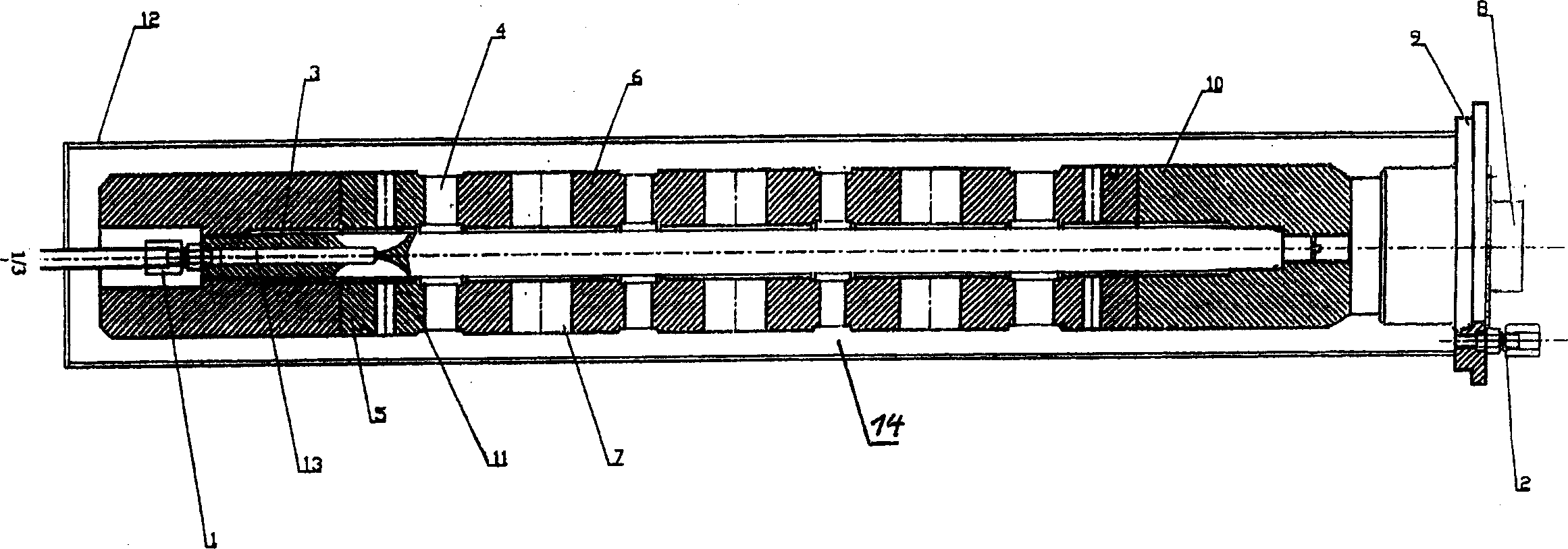
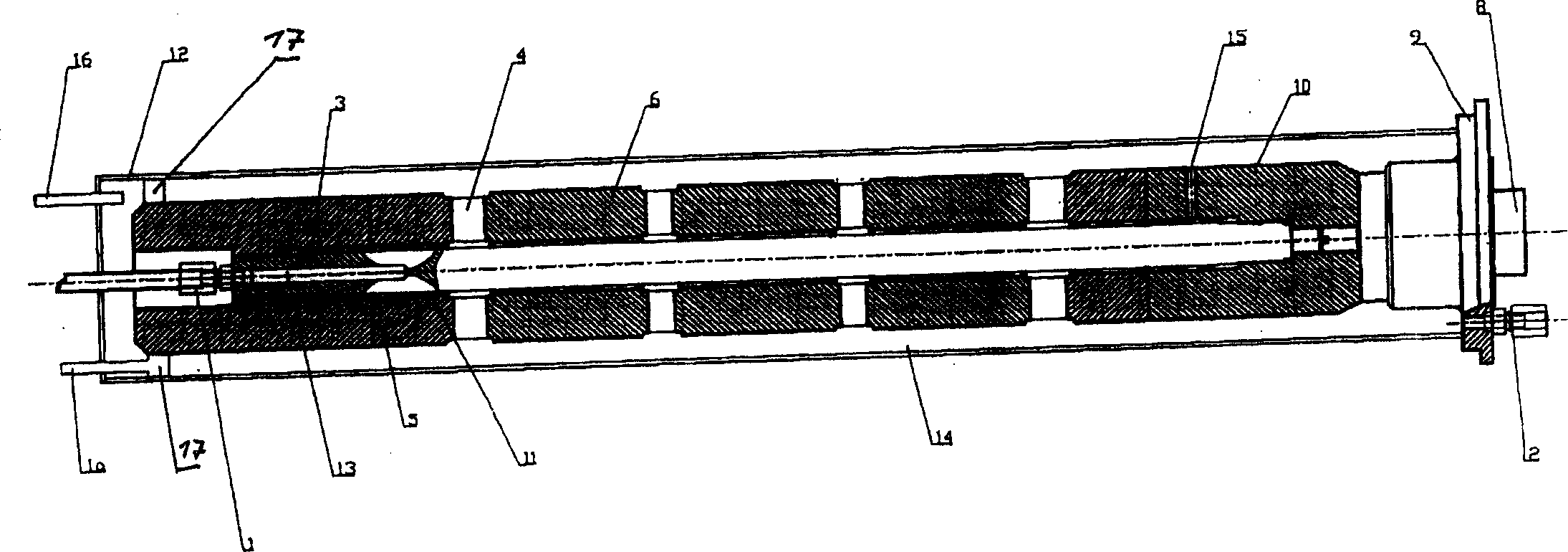
[0036] figure 1 A schematic longitudinal cross-section of an ultrasound transducer is shown, including a device for cooling the ultrasound transducer according to the invention. The ultrasound transducer is formed from cylindrical transducer bodies 5 , 6 and a piezoelectric stack 4 arranged between the end faces of the respective transducer body. Several of the transducer bodies 5 , 6 are formed into a single transducer body 6 in which a separate piezoelectric stack 4 is arranged on each end face. One of the individual piezoelectric stacks 4 is connected to one of the transducer bodies 5 and forms a lambda / 2 oscillator with either half of one of the single transducer bodies 6 or halves of both single transducer bodies 6 . The transducer bodies 5 , 6 have radially extending flow channels 7 . The transducer bodies 5 , 6 are arranged alternately with the piezoelectric stacks 4 on the tie rod 3 with an end thread. Such an arrangement is fixed and tensioned by two threaded end b...


PUM


Abstract

The invention relates to a method and a device for cooling ultrasonic transducers. The inventive device is characterised in that it consists of at least one piezo stack (4) and at least two cylindrical transducer bodies (5), which together with the piezo stack (4) form an lambda / 2 oscillator. In multiple transducer assemblies, two respective transducer bodies (5) can be combined to form a common transducer body (6) and the transducer bodies (5, 6) comprise flow channels (7), through which pressurised coolant can flow. The inventive method for cooling ultrasonic transducers is characterised in that the body of the ultrasonic transducer is traversed and / or surrounded by a pressurised coolant. This enables the heat that is generated in the transducers to be directly dissipated by convection. In addition the inventive elements enable the creation of a large common contact surface between the transducers and the coolant. The heat dissipation achieved is substantially more effective than in known methods and the inventive elements thus guarantee a high-performance continuous operation.

Description

technical field [0001] The invention relates to a method and a device for cooling an ultrasonic transducer, which method and device have the technical features of claims 1 and 6 . Background technique [0002] During the operation of an ultrasonic transducer, energy losses are converted into heat. These losses are due on the one hand to electrical losses and on the other hand to the internal friction that occurs within the piezoelectric element when electrical energy is converted into mechanical energy. Different methods are known to effectively remove the heat generated. Traditional cooling systems transfer heat by conduction or convection. In many cases, these two operating principles are used in combination. [0003] High power ultrasound transducers, which inherently have large amplitudes, are difficult to cool because a large amount of heat must be dissipated without generating more friction or additional heat. Since coolants are prone to ca...

Claims


Application Information

Patent Timeline
IPC IPC(8): G10K11/00B06B1/06
CPCB06B1/0611G10K11/004G10K11/00
Inventor 哈拉尔德·希尔舍
Owner DR HIELSCHER
Learn More