Plasma zero-groove cutting equipment and method

A cutting equipment, zero groove technology, applied in the direction of plasma welding equipment, welding equipment, metal processing equipment, etc., can solve problems such as unreachable, expensive, eliminate taper, etc., achieve compact design, high application value, adjustment handy effect

Inactive Publication Date: 2006-03-08
DALIAN HUARUI HEAVY IND CNC EQUIP
View PDF0 Cites 5 Cited by
  • Summary
  • Abstract
  • Description
  • Claims
  • Application Information

AI Technical Summary

Problems solved by technology

However, there is a serious cutting quality defect in the plasma cutting machine. At present, when using an ordinary plasma cutting machine to cut various metal sheets, the cutting surface of the workpiece is not a right-angled surface, but the cutting surface of the workpiece is a beveled surface with a V-shaped cut. To 90°, there is a certain angle or groove. This deficiency is an inherent characteristic of plasma cutting technology and a defect that cannot be overcome by plasma cutting machines. Normal cutting requires that the cutting surface of the cutting workpiece is a vertical surface, and the incision is 90°
In the past, in order to reduce the cutting bevel of parts, it is necessary to improve the quality of the plasma arc—reduce its taper angle, which has high cost and poor stability in improving the performance of the plasma arc, and theoretically, it is impossible to completely eliminate the taper.
In order to eliminate the bevel on the workpiece, manufacturers of plasma cutting machine power supplies are now trying to change the shape of the ion flow and minimize the angle of the bevel. For example, fine plasma cutting machines are such products. Small, but the price is very expensive. This kind of cutting machine is 5-10 times the price of ordinary plasma cutting machines, or even more expensive, and the actual cutting bevel is still about 1.5°-3°

Method used


Image

  • Plasma zero-groove cutting equipment and method
  • Plasma zero-groove cutting equipment and method

Examples


Embodiment Construction

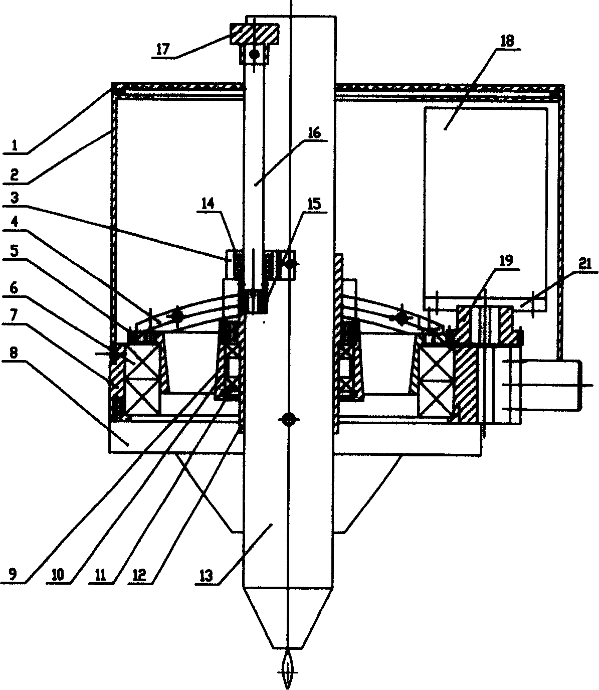
[0011] as attached figure 1 As shown, the servo motor 11 adopts Panasonic MSMA042A1G, the motor power is 400W, and 3000 revolutions per minute. Pinion, module 1, number of teeth 35. The ring gear module is 1 and the number of teeth is 160. Outer bearing 61826-2Z, 2 pcs. Inner bearing 61810-2LS, 2 pcs. Angle adjustment bearing 14 is 61800-2LS, 2 pieces. Cutting torch 13 adopts MAX200. Arch beam 4 radius outer arc R190mm. Select the thickness of the cutting steel plate to be 20mm, rotate the angle adjustment handwheel to adjust the angle, and the angle of the cutting torch is 5°. During adjustment, the cutting torch 13, the cutting torch cover 12, the inner bearing 11, the cutting torch seat 9 and the angle adjustment device slide together on the arched beam 4 around the center of the arched beam 4, no matter how much the angle is, the cutting point of the cutting torch 13 Invariant with respect to the race 5, always at the same point. On the CNC cutting machine, the ser...


PUM


Abstract

A plasma cutting device without groove and its method is disclosed, which comprises angle-adjusting base, arc girder, ring gear, outer gear, seat ring, bottom cleading, base of cutting torches, inner bearing, inner gear, bushing of cutting torches. The ring gear meshes with the pinion, outer bearing is set in the seat ring, and the ring gear is installed at outer bearing, the arc girder connects with the ring gear, there has an angle adjustment base on the torch base. The inclination angle of cutting torches can be adjusted via turning the angle-regulating handwheel, the ring gear runs by servo motor driving via pinion. At the same time, the arc girder, base of cutting torches, inner bearing, inner gear, bushing of cutting torches, cutting torches and angle-regulating device synchronousely rotate with the ring gear around same axes, the cutting torches can freely rotate in the bearing reverse with ring gear direction, which can release the enlacing force of cable and all sorts of tubes. Advantages: compact structure, simple operation, easy to adjust and without groove.

Description

technical field [0001] The invention belongs to the technical field of numerical control plasma cutting machine equipment manufacturing, in particular to a plasma zero-slope cutting equipment and method, which are suitable for cutting carbon steel and non-ferrous metal plates. Background technique [0002] Using a plasma cutting machine to cut the plate is faster than a flame cutting machine, with better quality and smooth cutting surface. For carbon steel with a thickness of less than 25mm, the plasma cutting speed is 3 to 5 times that of flame cutting. However, there is a serious cutting quality defect in the plasma cutting machine. At present, when using an ordinary plasma cutting machine to cut various metal sheets, the cutting surface of the workpiece is not a right-angled surface, but the cutting surface of the workpiece is a beveled surface with a V-shaped cut. To 90°, there is a certain angle or bevel. This deficiency is an inherent characteristic of plasma cutting t...

Claims


Application Information

Patent Timeline
Patent Type & Authority Applications(China)
IPC IPC(8): B23K10/00
Inventor 孙宝林王庆章刘静曾立新
Owner DALIAN HUARUI HEAVY IND CNC EQUIP
Why Eureka
Try Eureka