Buoyancy generating equipment

A power generation equipment and buoyancy technology, applied in hydropower, mechanical equipment, engine components, etc., can solve problems such as inability to complete automatic circulation, unreasonable design of buoys, low work efficiency, etc., to achieve small maintenance workload, good effect, and low consumption small energy effect

Inactive Publication Date: 2006-03-08
彭之桐
View PDF12 Cites 9 Cited by
  • Summary
  • Abstract
  • Description
  • Claims
  • Application Information

AI Technical Summary

Problems solved by technology

[0016] However, the buoyancy generators in the public literature have some shortcomings. Some have complex mechanisms, and the floats need to be pushed; some buoys are unreasonably designed and cannot complete automatic circulation;

Method used


Image

  • Buoyancy generating equipment
  • Buoyancy generating equipment

Examples


Embodiment Construction

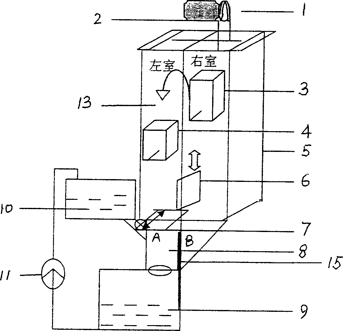
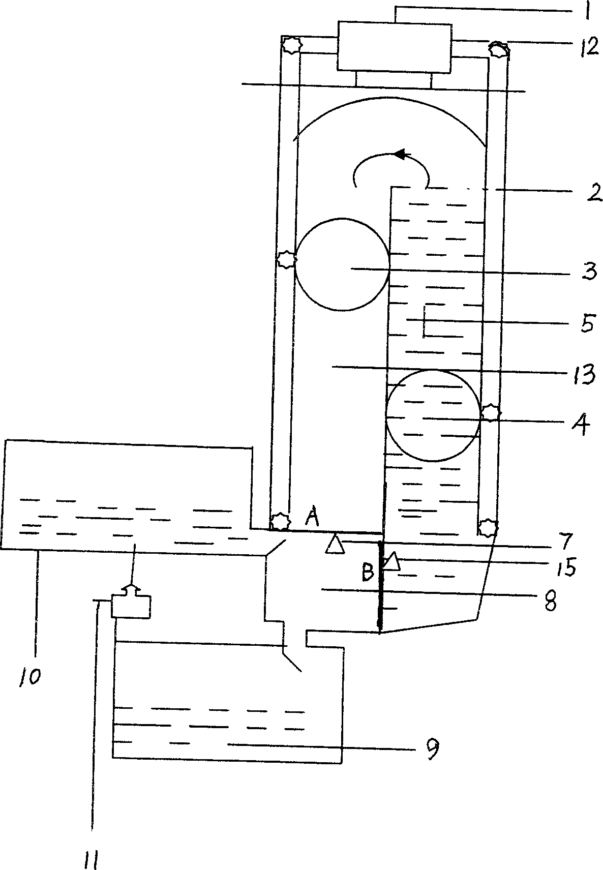
[0035] Such as figure 1 As shown, the buoyancy power generation equipment includes a high-level pool 10, a low-level pool 9, floats 3, 4, and a circulation control tank that provides work for the floats. The control tank is cylindrical, and the floater is spherical. 2. The chain drive belt 2 is connected to the generator 1. The circulation control tank is a container divided into two chambers, with a partition installed in the middle. One side of the partition is the liquid chamber 5 (right chamber), and the other side is for the free fall of the float. Chamber 13 (left chamber), the bottom of the free fall working chamber 13 has a float transfer chamber 8, the float transfer chamber 8 has a control door 7 (A) and a control door 6 (B), and the control door (A) controls the free fall chamber 13 is opened, the control door (B) controls the opening of the liquid chamber 5, and the float transfer studio 8 also has a connecting door that communicates with the high pool 10 and the l...


PUM


Abstract

This invention discloses a float generation equipment, which contains circulation control groove, float, connection mechanism and generator etc, wherein the circulation control groove is a container separated into two chambers by partition board, one cavity is filled with liquid, another cavity is the free falling body work chamber with a float transferring chamber in bottom which has control gate, connecting gate, high level pool, low level pool and control pump, plurality of floats are set circulation control groove and connected with generator by connection mechanism, the float drives connection mechanism in lifting process of circulation control groove to make generator continuously generate.

Description

technical field [0001] The present invention relates to a device for generating electricity by using natural force, especially a device for generating electricity by using the buoyancy of water, oil or other liquids. Background technique [0002] At present, my country's electricity sources are mainly thermal power and hydropower, and at the same time, nuclear power, wind power, photovoltaic and tidal power are actively developed. The total installed capacity of the country is about 600 billion KW. To build a 500,000-kilowatt power plant, the construction time of hydropower projects will take about 6 years, with an investment of about 5 billion yuan; thermal power projects will take about 5 years, with an investment of about 3 billion yuan, and thermal power will not only pollute the environment, but also need 20 years to complete. Cost recovery; nuclear power generation requires an investment of about 8 billion yuan, and nuclear waste treatment is very troublesome, and the ...

Claims


Application Information

Patent Timeline
Patent Type & Authority Applications(China)
IPC IPC(8): F03B17/02
CPCY02E10/20
Inventor 彭之桐许美玉
Owner 彭之桐
Why Eureka
Try Eureka