Steam compression type refrigerating economizer system
A vapor compression and economizer technology, applied in irreversible cycle compressors, compressors, refrigerators, etc., can solve the problem of poor single-phase liquid conduction performance of the throttle valve, inability to achieve system miniaturization, and evaporator heat exchange efficiency. Low problems, to achieve the effect of miniaturization, reduction in quantity, and reduction in control difficulty
- Summary
- Abstract
- Description
- Claims
- Application Information
AI Technical Summary
Problems solved by technology
Method used
Image

Examples
Embodiment 1
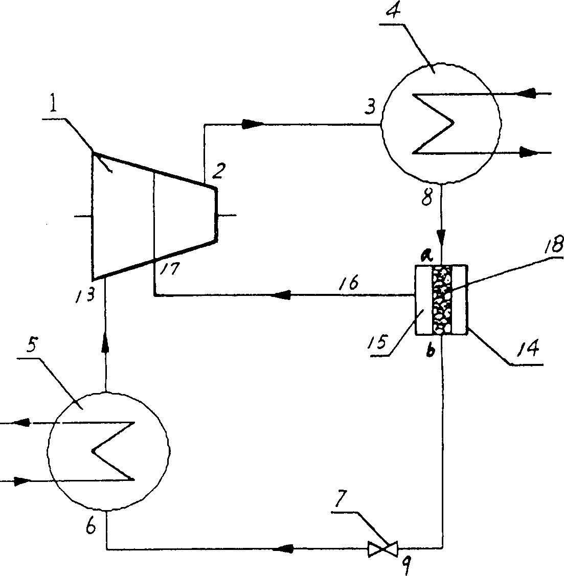
[0026] Embodiment 1: In the refrigerant circulation system of the above-mentioned A, the membrane evaporation separation device 14 is formed by a permeability of 1*10 -2 --5*10 -4 L / min.cm 2 .Pa sintered metal hollow tube separation membrane and a copper shell encapsulating the metal hollow tube separation membrane. The cavity between the shell and the metal hollow tube separation membrane is a refrigerant evaporation chamber. Both ends of the refrigerant liquid inlet and outlet are directly installed.
Embodiment 2
[0027] Embodiment 2: In the refrigerant circulation system of the above-mentioned A, the membrane evaporation separation device 14 is formed by a permeability of 1*10 -2 --5*10 -4L / min.cm 2 The ceramic tube separation membrane of .Pa and the copper shell encapsulating the ceramic tube separation membrane, the cavity between the shell and the ceramic tube separation membrane is the refrigerant evaporation chamber, and the two ends of the separation membrane are directly equipped with refrigeration Agent liquid inlet and outlet.
Embodiment 3
[0028] Embodiment 3: In the refrigerant cycle system of the above-mentioned A, the membrane evaporation separation device 14 is formed by a permeability of 1*10 -2 --5*10 -4 L / min.cm 2 .Pa polypropylene fiber tube separation membrane and a copper shell encapsulating the fiber tube separation membrane. The cavity between the shell and the polypropylene fiber tube separation membrane is the refrigerant evaporation chamber. Both ends are directly equipped with refrigerant liquid inlet and outlet.
PUM
 Abstract
Description
Claims
Application Information