Two-way heat transfer heat pipe

A two-way heat transfer and heat pipe technology, applied in indirect heat exchangers, lighting and heating equipment, etc., can solve problems such as inability to work, and achieve the effect of solving energy storage problems and low cost

Inactive Publication Date: 2006-03-08
淄博绿能环保设备科技有限公司
View PDF0 Cites 7 Cited by
  • Summary
  • Abstract
  • Description
  • Claims
  • Application Information

AI Technical Summary

Problems solved by technology

However, it is precisely because of the above reasons that when there is a difference in height between the evaporation section of the heat pipe and the condensation section of the heat pipe, a one-way heat conduction characteristic occurs, that is, the evaporation section is on the bottom and the condensation section is on the top, otherwise it cannot work.

Method used


Image

  • Two-way heat transfer heat pipe
  • Two-way heat transfer heat pipe
  • Two-way heat transfer heat pipe

Examples


Embodiment Construction

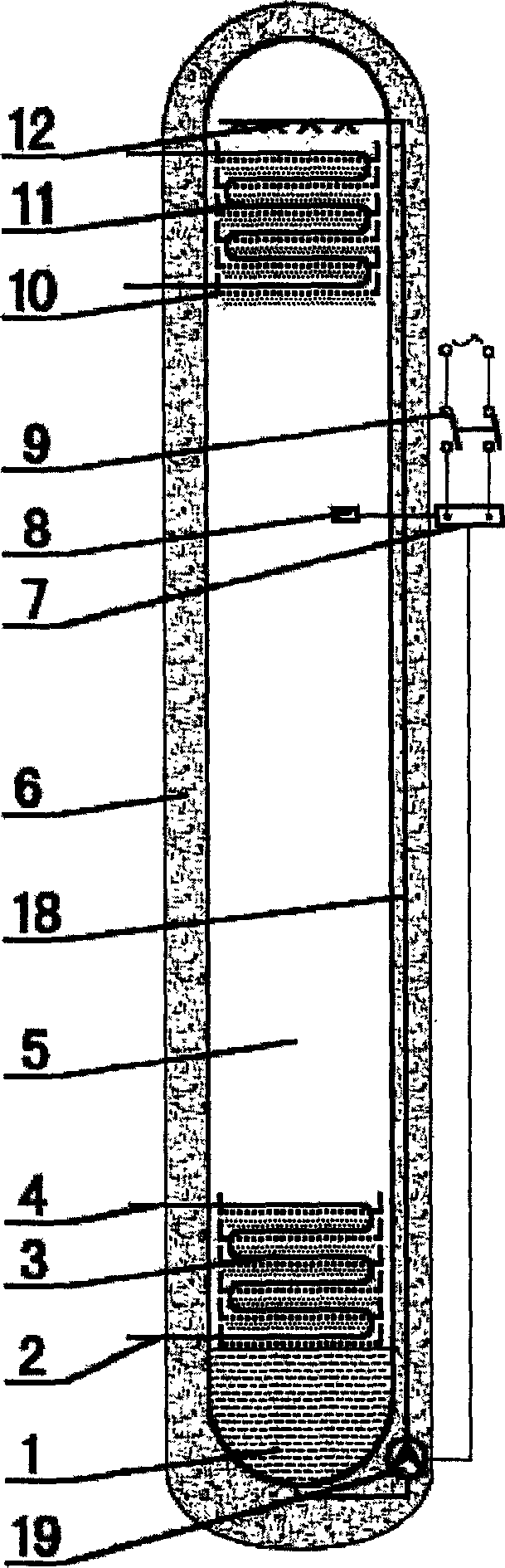
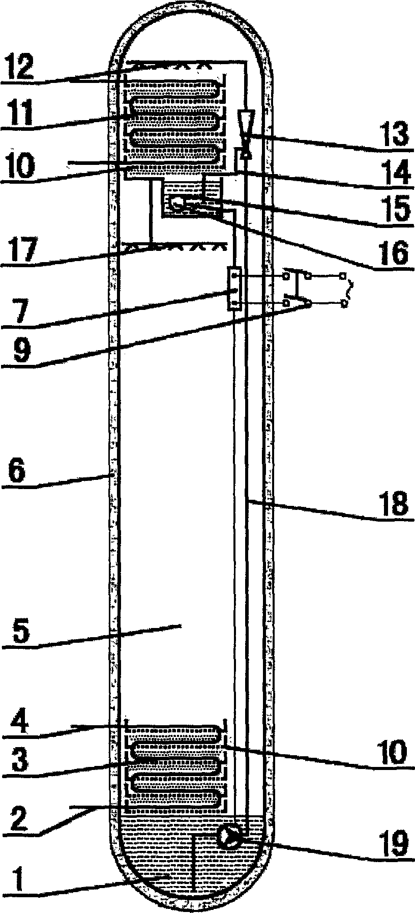
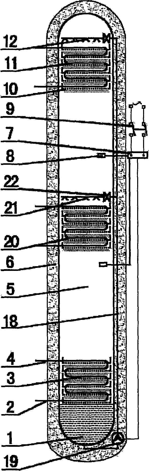
[0032] exist figure 1 Middle: When the lower heat exchanger 3 of the two-way heat transfer heat pipe is the evaporating section, and the upper heat exchanger 11 is the condensation section, the two-way heat transfer heat pipe is a passive heat pipe, and no external power is required. The effect of gravity can make the upper heat exchanger 11 The phase-change heat medium 1 condensed on the top flows back to the lower displacement heat exchanger 3 to realize heat conduction. During this process, the medium passing through the lower heat exchanger 3 is cooled, and the medium passing through the upper heat exchanger 11 is heated. When the lower displacement heat exchanger 3 is the condensation section and the upper displacement heat exchanger 11 is the evaporation section, the condensed phase-change heat medium 1 accumulates at the lower end of the heat pipe, and the phase-change heat medium 1 is pumped by the phase-change heat medium pump 19. Enter the liquid distribution device...


PUM


Abstract

A bi-directional conductive heat pipe, which contains closed casing, heat exchanger, phase change exchange medium pump, liquid distributor, electric appliance controller, phase change exchange medium, and thermo- insulation material, wherein the closed casing installed with low position exchanger and at least one high position exchanger, the casing cavity filled with phase change exchange medium after pumping vacuum, the thermo-insulation material covered on the non exchange surface of casing, the phase change exchange medium pump controlled by electric appliance set in heat pipe, the heat exchanger covered heat conductive and liquid storage absorbing material on pipe wall. Said invention can realize bi directional heat conduction.

Description

Technical field [0001] The invention relates to a bidirectional heat transfer heat pipe, which belongs to the field of heat transfer elements. Background technique [0002] At present, the known heat pipe is a passive heat transfer element with extremely high thermal conductivity, and has a unidirectional heat conduction characteristic. The heat pipe uses the principle of phase change and capillary action, so that its heat transfer efficiency is hundreds to thousands of times higher than that of pure copper of the same material. The heat pipe is a vacuum tube, and the working liquid injected inside is the medium of heat transfer. Because after the inside of the heat pipe is evacuated, liquid is injected before sealing, so the pressure inside the heat pipe is determined by the vapor pressure after the working liquid evaporates. As long as the surface of the heat pipe is heated, the working liquid will evaporate. The temperature and pressure of the steam at the evaporating ...

Claims


Application Information

Patent Timeline
Patent Type & Authority Applications(China)
IPC IPC(8): F28D15/02
Inventor 徐宝安
Owner 淄博绿能环保设备科技有限公司
Why Eureka
Try Eureka