

Bending machine control method and system
A control method and bending machine technology, applied in the direction of general control system, control/regulation system, computer control, etc., can solve the problems of only position programming, inconvenient mold, high price, etc., and achieve the reduction of components and connections, debugging Ease of use and improved reliability
- Summary
- Abstract
- Description
- Claims
- Application Information
AI Technical Summary
Problems solved by technology
Method used
Image

Examples
Embodiment Construction
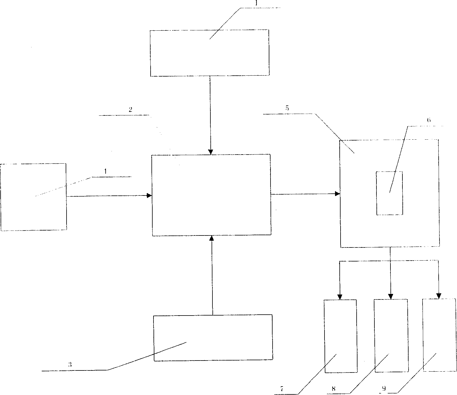
[0036] like figure 1 As shown, the present invention includes an X-axis photoelectric encoder 1, a special bending controller 2, a Y-axis photoelectric encoder 3, a machine tool electrical input 4, an electric control cabinet 5, a special driver 6 installed in the electric control cabinet, and a drive slide Block solenoid valve group 7, X-axis motor 8, Y-axis motor 9.
[0037] Machine tool electrical input 4 includes control mode 1, control mode 2, oil pump start signal, top dead point, shift point, clamping point, bottom dead point, pedal up, pedal down, programming lock, step change signal, X axis front Limit, X-axis rear limit, Y limit, Y-axis rear limit, safety light curtain. Among them, control mode 1 and control mode 2 are used to select the working mode of the slider: single, continuous, jog.
[0038]When the bending special controller receives the start signal of the oil pump, the system can work. As long as it is not in the jog working state, the system can be opera...
PUM
 Abstract
Description
Claims
Application Information