Method and receiver for receiving an ultra wide band signal

A receiver, ultra-wideband technology, applied in transmission systems, electrical components, etc., can solve the problems of complicated accuracy and timing jitter, low synchronization bandwidth of precise clocks, inability to track time jitter, etc., to reduce cost and/or size. and/or complexity, reduction of additional or replacement requirements, effect of data error rate improvement

Inactive Publication Date: 2006-03-08
MOTOROLA INC
View PDF0 Cites 2 Cited by
  • Summary
  • Abstract
  • Description
  • Claims
  • Application Information

AI Technical Summary

Problems solved by technology

Although this time synchronization can compensate for some time jitter of the received signal or the local oscillator, the requirement for an accurate clock requires a very low synchronization bandwidth which cannot track most of the time jitter
Moreover, timing error detectors, such as lead-lag correlators, are in practice unable to produce sufficiently accurate timing error estimates for the extremely short-duration data pulses of UWB signals, so that only coarse compensation of time jitter is practical
Consequently, the design of current UWB communication systems is limited or complicated by oscillator accuracy and timing jitter, resulting in reduced performance and / or costly, complex and / or large numbers of oscillators and such communication units

Method used


Image

  • Method and receiver for receiving an ultra wide band signal
  • Method and receiver for receiving an ultra wide band signal
  • Method and receiver for receiving an ultra wide band signal

Examples


Embodiment Construction

[0042] The following description focuses on embodiments of the invention applied to pulse position modulated (PPM) ultra wideband (UWB) signals. However, it will be appreciated that the invention is not limited to this application, but may be applied to many other UWB signals, including for example pulse amplitude modulated (PAM) UWB signals or combined PAM and PPM signals.

[0043] For the sake of simplicity and conciseness, the description in this paper focuses more on binary PPM-UWB. However, the principles described herein can be easily extended to eg m-ary PPM-UWB signals or any kind of PAM / PPM-UWB signals.

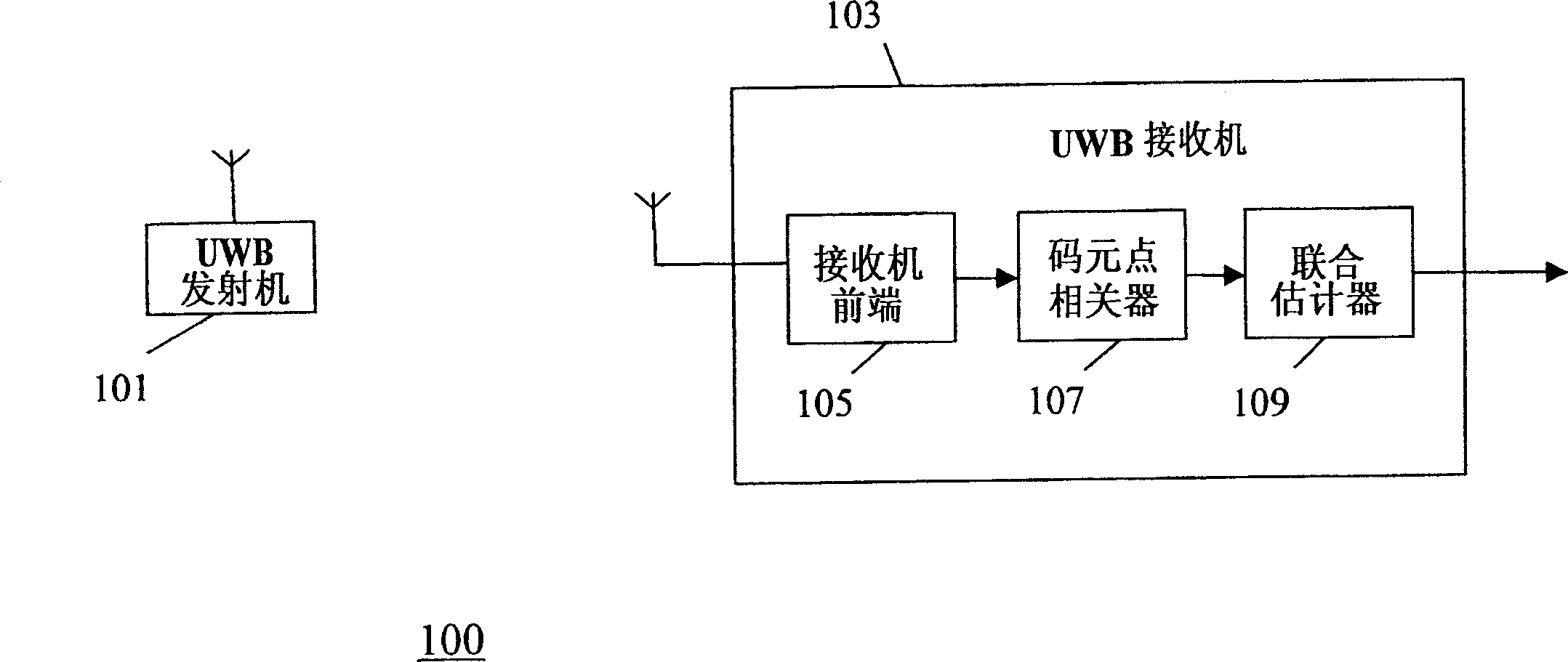
[0044] figure 1 A system 100 for transmitting UWB signals according to one embodiment of the present invention is described.

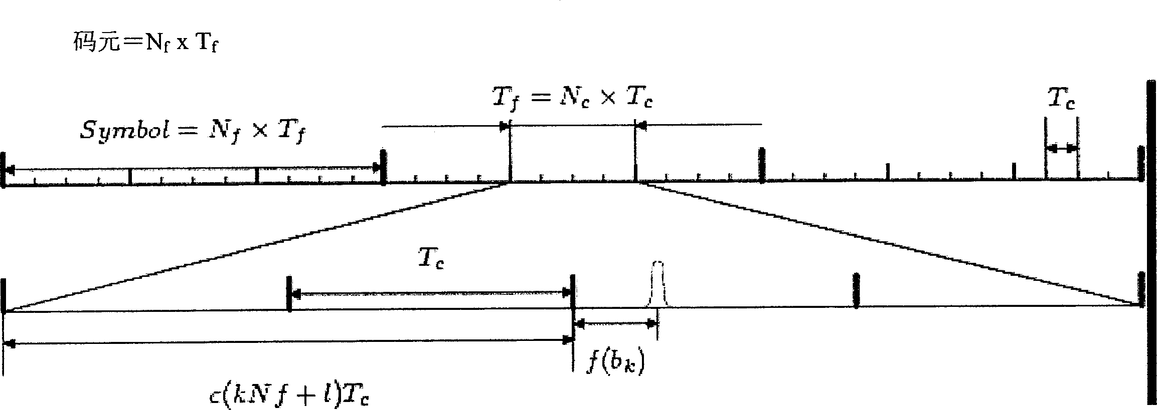
[0045] The system 100 includes a UWB transmitter 101, which in this exemplary embodiment generates UWB signals according to the specifications of IEEE802.15.3a and / or IEEE802.15.4a. exist figure 2 The format of the transmitted signal is ...


PUM


Abstract

Areceiver (103) for receiving an Ultra Wide Band (UWB) signal comprises a receiver front end (105) coupled to symbol point correlators (107). The symbol point correlators (107) comprise a first plurality of correlators which generates correlated signal values around a first symbol decision point of a first symbol by correlating the received UWB signal with a local replica. The first plurality of correlators are time offset with respect to each other to generate first time offset correlated signal values. The time offsets are typically significantly less than the timing jitter of transmit and receive oscillators. The symbol point correlators (107) are coupled to a joint estimator (109) which determines a symbol value of the first symbol in response to the first time offset correlated signal values by joint detection of the symbol value and a time offset of the UWB signal. The invention may effectively reduce time jitter noise to a value determined by the relative time offset between the correlators.

Description

technical field [0001] The present invention relates to a method and receiver for receiving ultra-wideband (UWB) signals, more particularly but not exclusively, to a method for receiving pulse position modulation (PPM) UWB signals or pulse amplitude modulation (PAM) UWB signals method and receiver. Background technique [0002] In recent years, wireless data communication in home and business environments has become increasingly commonplace. A new wireless transmission technology called ultra-wideband (UWB) transmission has been proposed. UWB signals are generated by sending information in very short data pulses of typical 10-1000 picosecond duration, resulting in bandwidths of transmitted signals of several gigahertz. High data rates can be obtained through UWB signals, and because the bandwidth is very large, the spectral power density is relatively low. Consequently, the interference and susceptibility to narrowband interference from other signals in the frequency rang...

Claims


Application Information

Patent Timeline
Patent Type & Authority Applications(China)
IPC IPC(8): H04B1/707H04B1/69
CPCH04B1/69H04B1/709
Inventor 韦罗尼克·比泽纳克-塞蒂内里戴维·巴特曼马尔茨·G·伯纳德·德·库维尔穆罕默德·卡蒙皮埃尔·迪阿默莱
Owner MOTOROLA INC
Why Eureka
Try Eureka