

Gas liquid mixing apparatus by jet circulation reaction characteristics
A gas-liquid mixing and circulating reaction technology, applied in the directions of fluid mixers, mixers, mixing methods, etc., can solve problems such as the limitation of gas-liquid mixing efficiency, and achieve improved gas-liquid mixing effect, efficiency, and gas-liquid mixing. performance effect
- Summary
- Abstract
- Description
- Claims
- Application Information
AI Technical Summary
Problems solved by technology
Method used
Image

Examples
Embodiment Construction
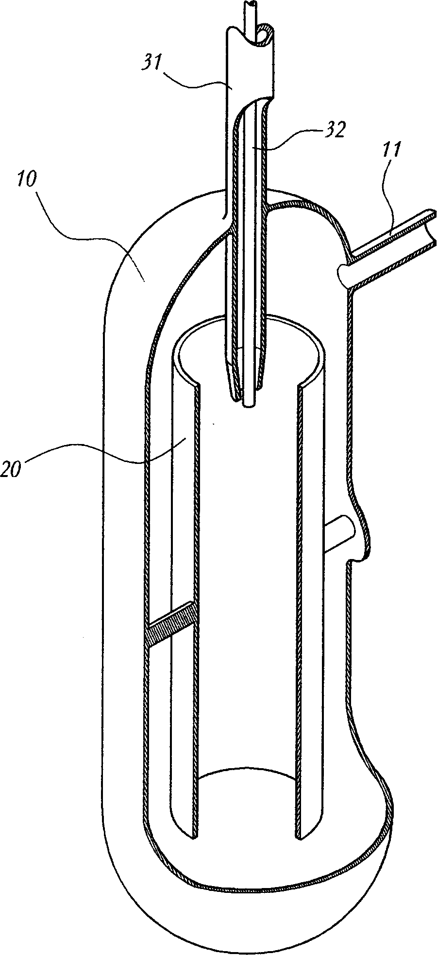
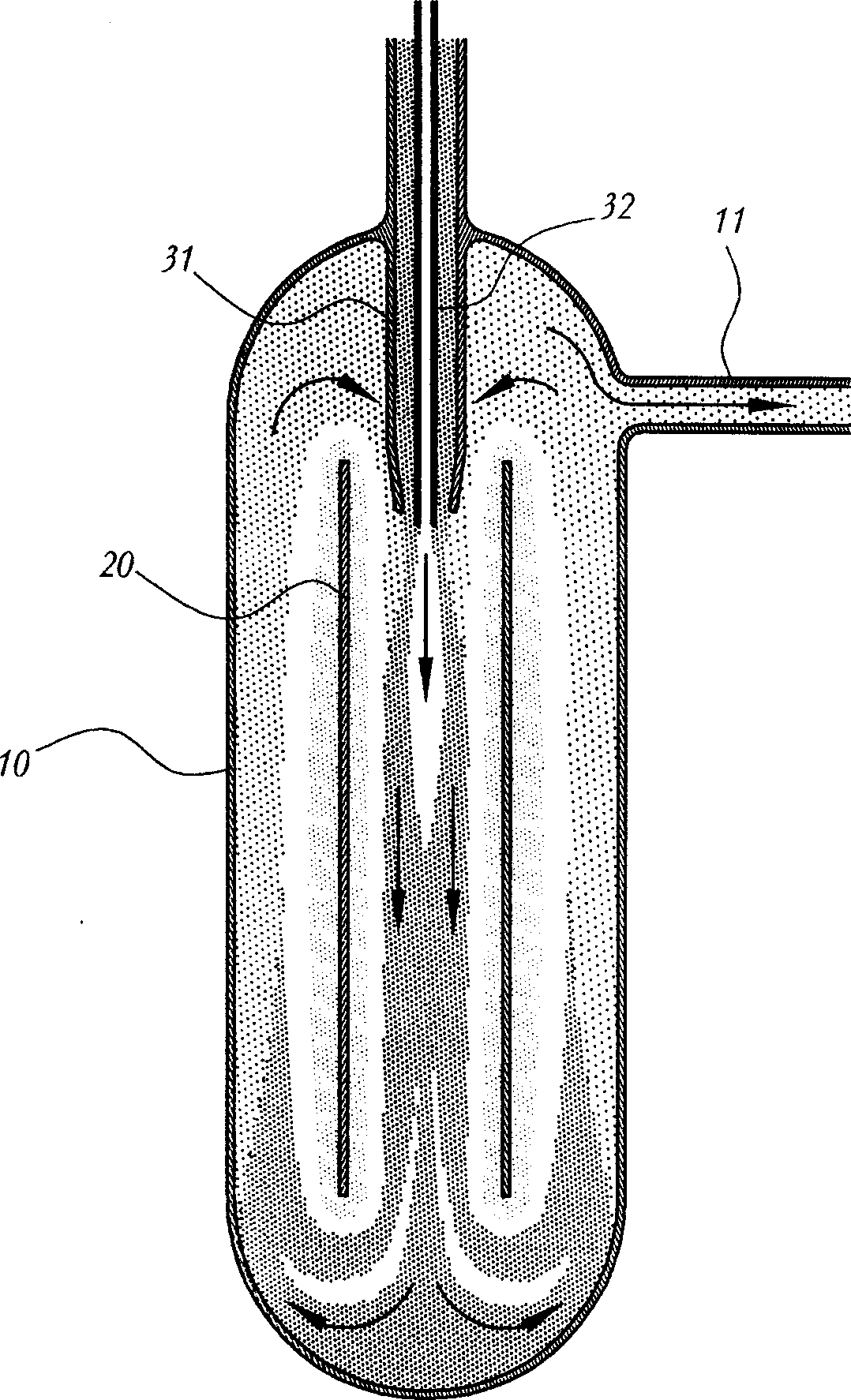
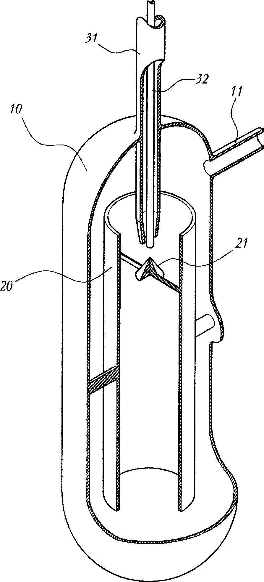
[0024] The present invention as image 3 As shown, it has the structure that a conical diffuser 21 is installed inside the induction pipe 20 provided in the treatment tank 10. When in action, the liquid and gas inside the treatment tank 10 form as Figure 5 flow shown.
[0025] The tip of the conical diffuser 21 points to the gas inlet pipe 32 and is arranged directly below the gas inlet pipe 32 . The way that the diffuser 21 is fixed in the induction tube can be adopted as image 3 The way shown is connected with induction tube 20, and as Figure 4 The way shown is connected with the liquid inlet pipe 31. It can be selected under conditions such as various planned flow rates and sizes of various liquid input pipes 31 and induction pipes 20, but it is hoped that the flow resistance of the liquid and gas in the treatment tank 10 is the least.
[0026] Figure 5 It shows the flow of liquid and gas in the processing tank 10 in the present invention. The treated water input ...
PUM
 Abstract
Description
Claims
Application Information