Signal transmission framework

A signal transmission and signal technology, applied in the field of signal transmission, can solve the problems of high switching rate of signal state, unsuitable for large-scale use, complex process and other problems, and achieve the effect of reducing switching rate, low cost and simple process

Inactive Publication Date: 2006-03-15
HONG FU JIN PRECISION IND (SHENZHEN) CO LTD +1
View PDF0 Cites 1 Cited by
  • Summary
  • Abstract
  • Description
  • Claims
  • Application Information

AI Technical Summary

Problems solved by technology

[0005] However, the cost of using capacitors to reduce the switching rate of the signal state is too high and the process is complicated, which is not suitable for mass use in manufacturing. Therefore, it is necessary to provide a low-cost high-speed signal transmission architecture suitable for manufacturing

Method used


Image

  • Signal transmission framework
  • Signal transmission framework
  • Signal transmission framework

Examples


Embodiment Construction

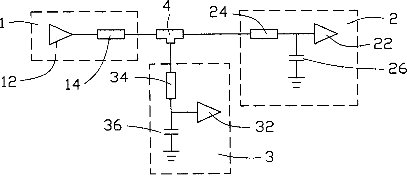
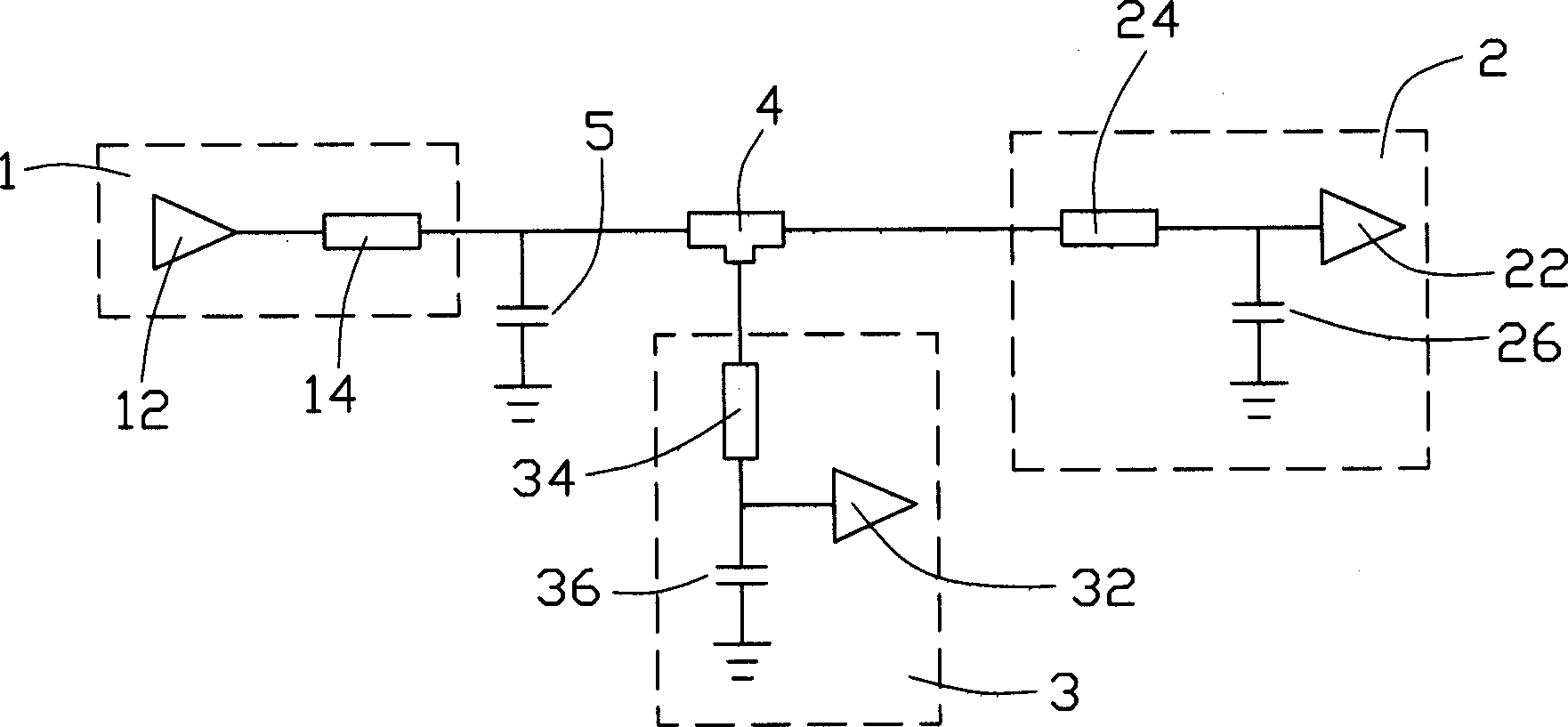
[0021] see Figure 9 , is the signal transmission architecture of the present invention, comprising a drive circuit block 1, a receiving circuit block 1 2 and a receiving circuit block 2 3, the receiving circuit block 1 2 and the receiving circuit block 2 3 are units connected in parallel, a main transmission line 4 and The driving circuit block 1, the receiving circuit block 1 2 and the receiving circuit block 2 3 are connected to each other. Wherein the driving circuit block 1 includes a driving circuit 12 and a transmission branch line 14, the receiving circuit one 2 includes a receiving circuit 22, a transmission branch line 24 and a terminal capacitor 26, and the receiving circuit two 3 includes a receiving circuit 32 and a transmission branch line 34 and a terminal capacitor 36 . The main transmission line 4 serves as the main transmission line, and each transmission branch line 14, 24, 34 serves as the internal signal transmission function of each circuit block. A mic...


PUM


Abstract

The invention includes a driving circuit module, a receiving circuit module, a main transmission line for connecting the driving circuit module and the receiving circuit module, and a micro strip structure connected between the driving circuit module and the receiving circuit module. The driving circuit module includes a driving circuit and a first transmission branch line used for transmitting signal output from driving circuit to the main transmission line. The receiving circuit module includes a receiving circuit and a second transmission branch line use for receiving signals from main transmission line and sending it to receiving circuit module. The micro strip structure functions like a capacitor. When the signal state in driving circuit module switches too fast, the micro strip structure is used to substitute for capacitor to decreases switching rate of signal.

Description

【Technical field】 [0001] The invention relates to a signal transmission technology, especially a technology for transmitting high-speed signals through a bus while maintaining the integrity of the high-speed signals. 【Background technique】 [0002] Under the action of the electric field, two conductors are coupled to each other. This coupling caused by the electric field is represented by mutual capacitance in the circuit model. There is mutual capacitance between any adjacent conductors. The closer the distance between the conductors, the greater the coupling. will be tighter. Similarly, under the action of a magnetic field, two conductors are coupled to each other, and this coupling caused by a magnetic field is represented by mutual inductance in the circuit model. Mutual capacitance and mutual inductance are the sources of interference. Mutual capacitance interference is manifested by mutual capacitance injecting a certain current at the crosstalk point on the victim l...

Claims


Application Information

Patent Timeline
Patent Type & Authority Applications(China)
IPC IPC(8): H04B3/02H05K1/00
CPCH05K1/162H05K1/0216H05K2201/09254H05K2201/09781H04L25/028
Inventor 许寿国刘建宏
Owner HONG FU JIN PRECISION IND (SHENZHEN) CO LTD
Why Eureka
Try Eureka