Piston pump

A piston pump and piston technology, applied in the direction of pumps, multi-cylinder pumps, pump components, etc., can solve problems such as deformation of the check valve seat, jeopardizing the reliability of the vehicle braking system, etc., and achieve an enlarged suction section and good suction characteristics. Effect

Active Publication Date: 2006-03-15
CONTINENTAL AUTOMOTIVE TECH GMBH
View PDF2 Cites 6 Cited by
  • Summary
  • Abstract
  • Description
  • Claims
  • Application Information

AI Technical Summary

Problems solved by technology

The disadvantage of this structure is that the extrusion force and connection force introduced into the sleeve may cause deformation of the seat of the check valve
This can jeopardize the operational reliability of the vehicle's braking system

Method used


Image

  • Piston pump
  • Piston pump
  • Piston pump

Examples


Embodiment Construction

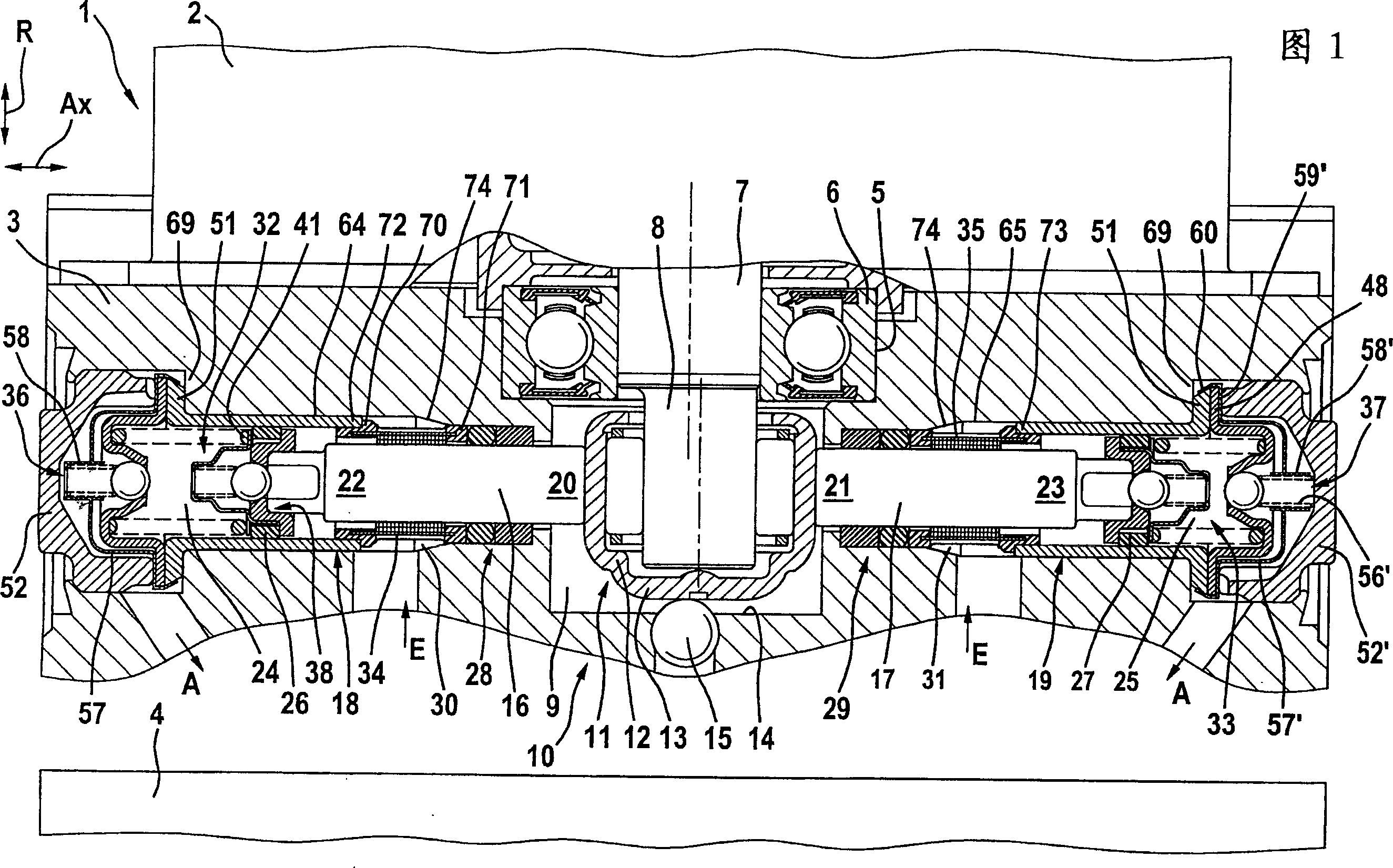
[0018] FIG. 1 shows an assembly 1 with a schematically shown drive 2, in particular an electric motor, which is flanged to a system for solenoid valves, channels, accumulator chambers or buffer chambers and Receiving part 3 of a piston pump 10 . On the opposite side of the receiving part 3 there is an electronic control unit 4 (shown only schematically). The shown assembly 1 is used in particular for slip control or driving stability control in a motor vehicle, but it can also be used for similar or different applications.

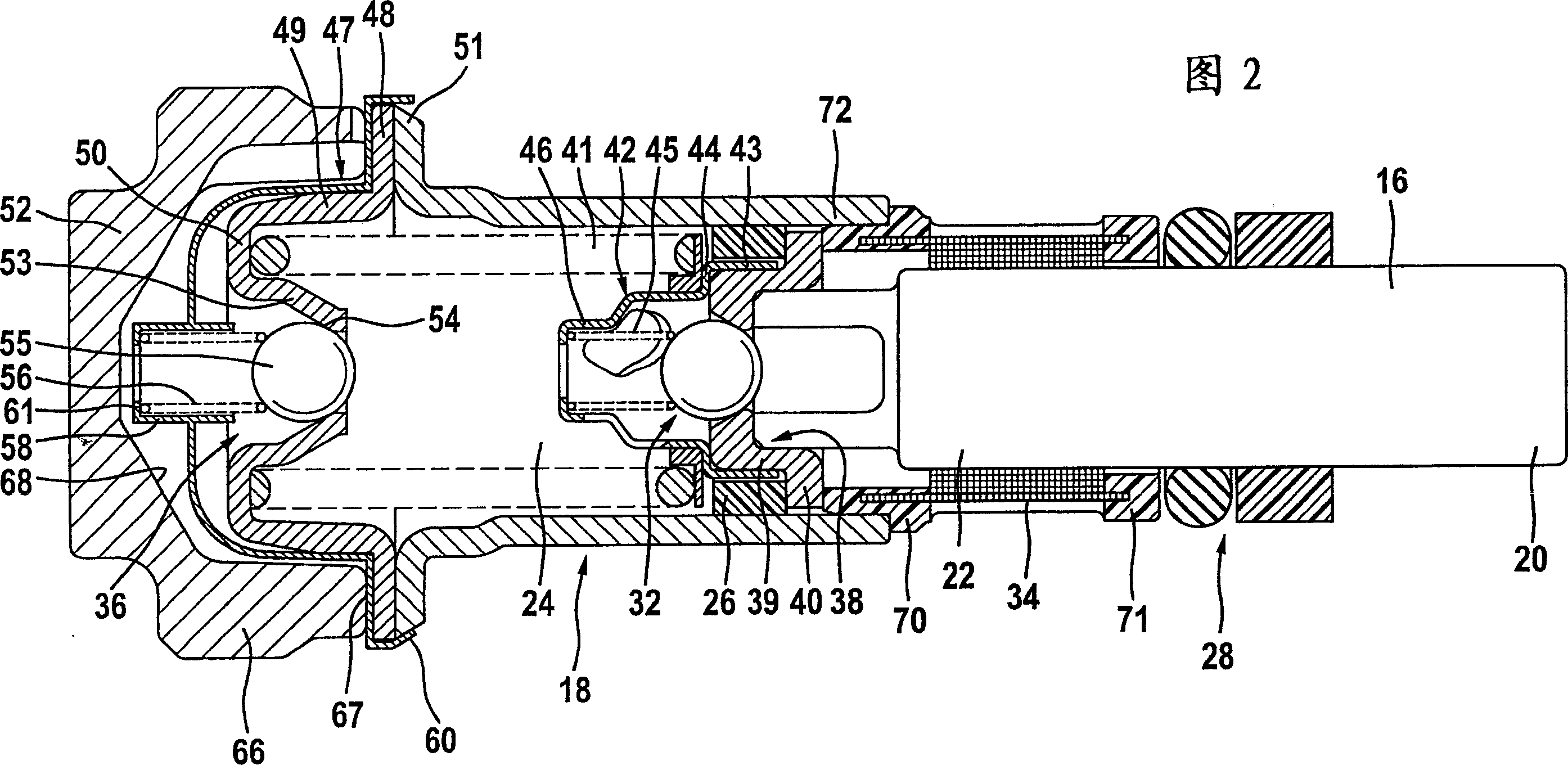
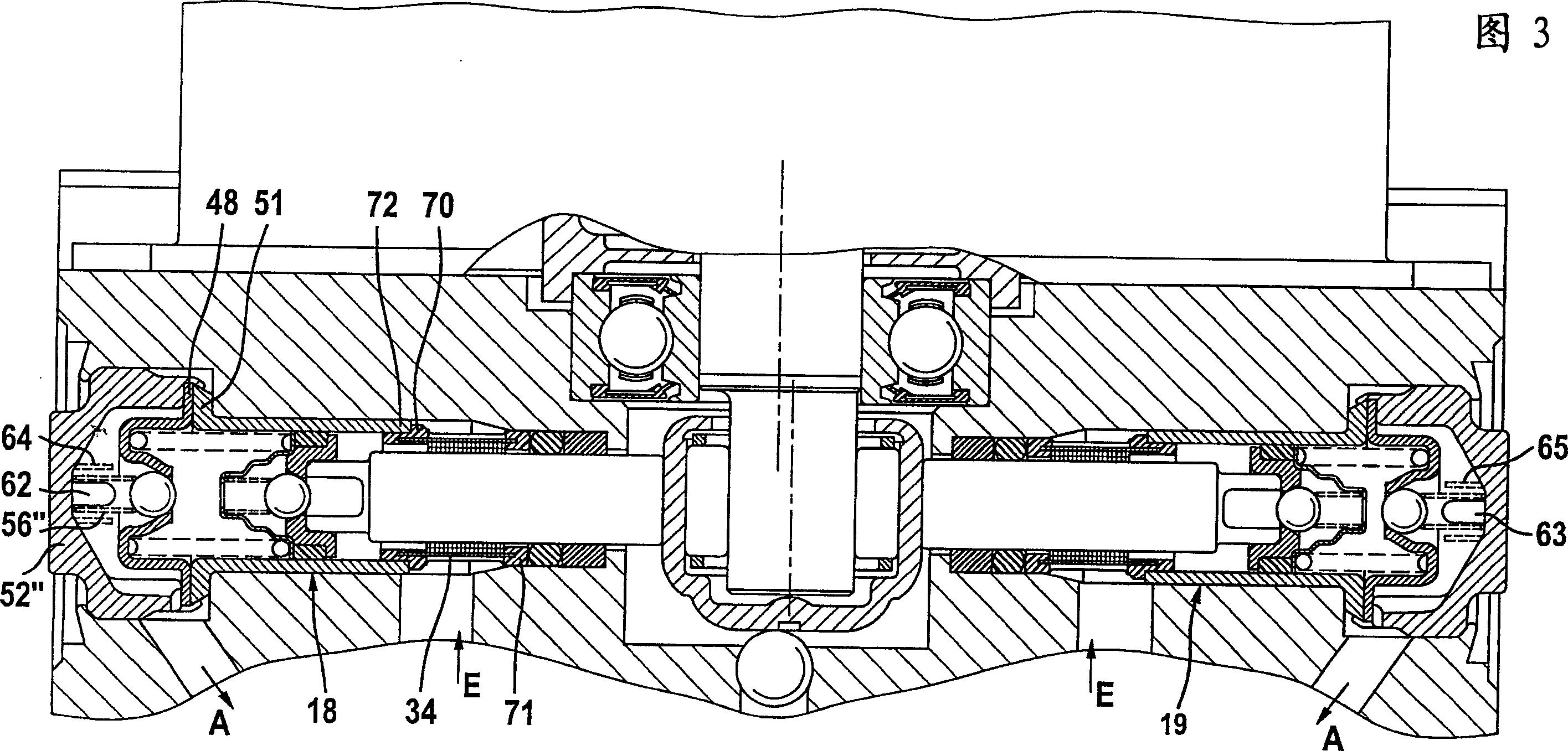
[0019] A preferably centrally located stepped bore 5 of the receiving part 3 accommodates a sealed rolling bearing 6 of a drive shaft 7 whose free end is designed as an eccentric 8 protruding into a crank chamber 9 of the stepped bore 5 . In principle, the eccentric can be ground directly on the drive shaft 7 or the motor shaft, or it can be designed as a separate component and fixed on the drive shaft. In order to prolong the operating life of the pump,...


PUM


Abstract

The invention relates to a piston pump (10) for supplying a pressure medium to at least one vehicle brake, a main cylinder, a pressure medium container, or a pressure medium store, of a regulated vehicle brake installation. The aim of the invention is to enable a piston pump (10) joined to a structural unit to be integrated into a receiving body (3) in a simple manner and in such a way that the construction space is reduced. The invention also aims to keep valve seats (38, 54) of check valves (32,33,36,37) as free as possible from pressing or fixing forces, in order to prevent the deformation or functional impairment thereof. To this end, a sleeve (18,19) has a radial flange for fixing between the closing element (52) and the receiving body (3).

Description

technical field [0001] The invention relates to a piston pump having the features stated in the preamble of claim 1 . Background technique [0002] A piston pump of this type is known, for example, from DE 10022811 A1, which comprises a sleeve held in a stepped bore. The bushing is pressed into the stepped bore by means of a closure member axially abutting against its bottom. The disadvantage of this structure is that the extrusion force and connection force introduced into the sleeve may cause deformation of the valve seat of the check valve. This can jeopardize the operational reliability of the vehicle's braking system. [0003] Such a piston pump is described in DE 19753083 A1. The closure part directly compresses the sleeve in the axial direction, thereby pressing the sleeve axially against the bore step. Forces introduced via the conical contact surfaces of the bushing and the bushing in the area of ​​the non-return valve cause deformation of the bushing in the are...

Claims


Application Information

Patent Timeline
Patent Type & Authority Applications(China)
IPC IPC(8): F04B1/04F04B53/10F04B53/16B60T17/02B60T8/40F04B53/12F04B53/20
CPCF04B1/0452F04B53/20F04B53/126F04B53/168F04B53/1002F04B1/0421B60T8/4031
Inventor D·丁克尔A·奥托H-G·岑特格拉夫
Owner CONTINENTAL AUTOMOTIVE TECH GMBH
Why Eureka
Try Eureka