

Temperature reducing device for vehicle tire
A technology of automobile tires and cooling devices, which is applied to vehicle parts, transportation and packaging, brakes, etc., can solve problems such as high risk, loss of control of the driving direction of the car, and tire blowouts, so as to improve safety, prevent tire blowouts, The effect of reducing friction
- Summary
- Abstract
- Description
- Claims
- Application Information
AI Technical Summary
Problems solved by technology
Method used
Image

Examples
Embodiment 1
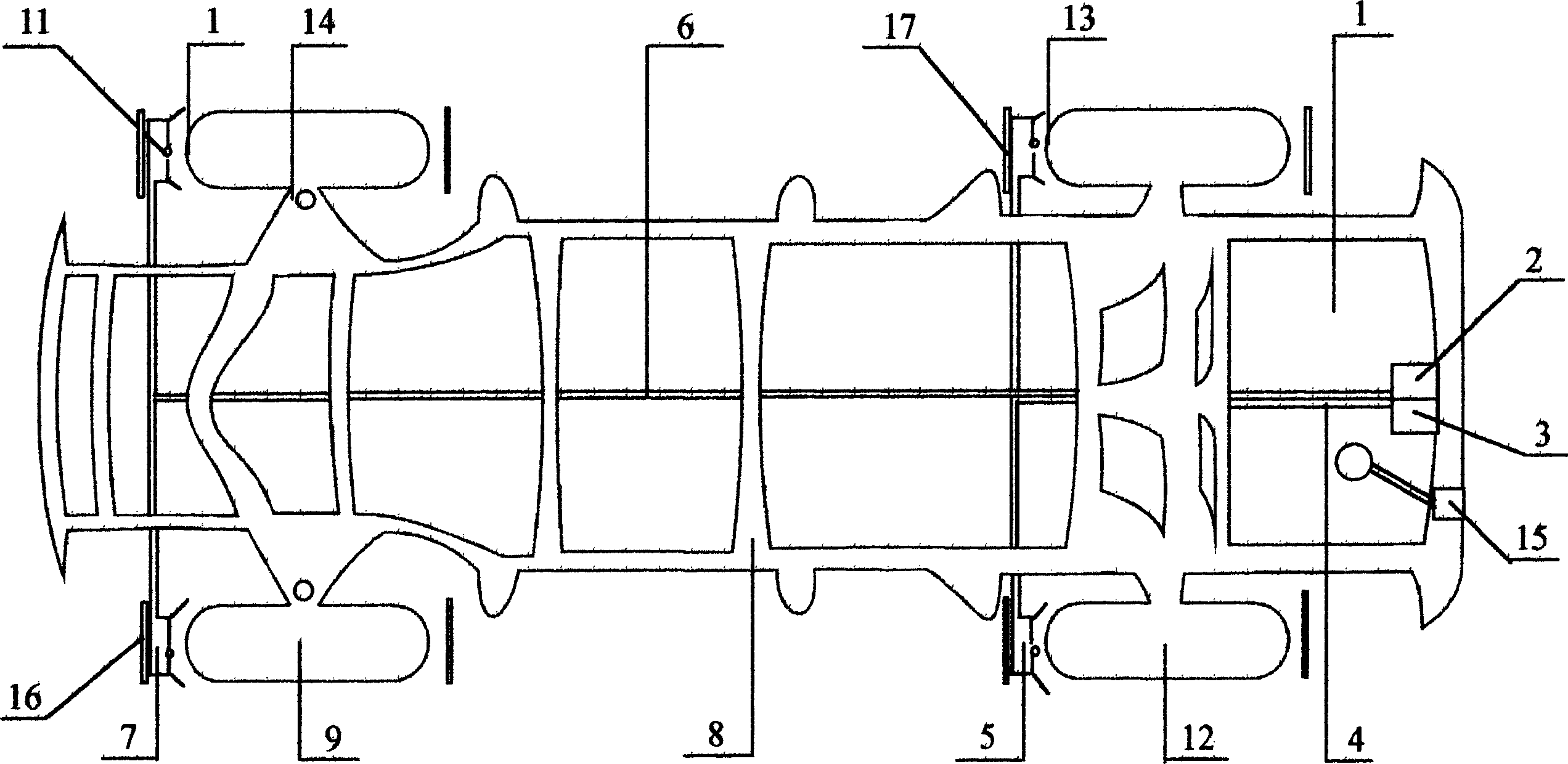
[0011] refer to figure 1 , the water tank 1 is located on the frame 8, the front wheel submersible pump 2 and the rear wheel submersible pump 3 are placed at the bottom of the water tank 1, one end of the front wheel water delivery pipe 6 is connected with the front wheel submersible pump 2, and the other end is connected with the front wheel water spray Mouth 7 is connected. Front wheel water nozzle 7 is fixed on the front wheel fender 16, and front wheel water nozzle 7 is at a certain distance from front tire crown 10, and the water outlet of front wheel water nozzle 7 is aimed at front tire crown 10. The water in the water tank 1 is extracted by the front wheel submersible pump 2, sprayed on the front tire crown 10 through the front wheel water delivery pipe 6, the front wheel water nozzle 7, and the water vaporization and heat dissipation on the front tire crown 10 makes the front tire 9 cool down. Simultaneously, the water on the front tire crown 10 is in contact with th...
Embodiment 2
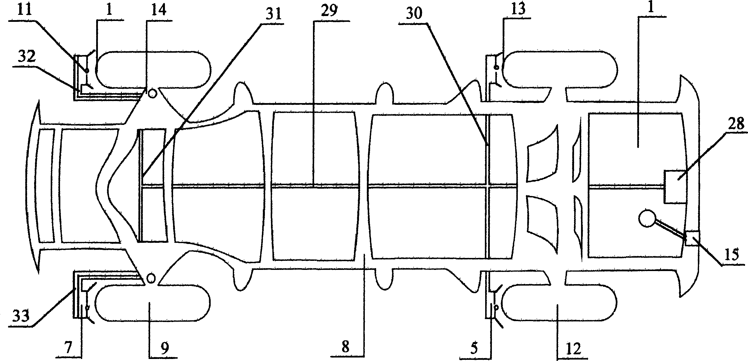
[0013] refer to figure 2 , the water tank 1 is located on the vehicle frame 8, the front and rear wheels share the submersible pump 28 and place it at the bottom of the water tank 1, one end of the main water delivery pipe 29 is connected with the front and rear wheel shared submersible pump 28, and the other end of the main water delivery pipe 29 is provided with a front wheel branch Water pipe 31 and rear wheel branch water pipe 30. The front wheel branch water delivery pipe 31 is connected with the front wheel water nozzle 7, and the front wheel water nozzle 7 is fixed on the steering system parts 14 through the bracket 33 and the hard water delivery pipe 32. The front wheel water nozzle 7 is connected with the front tire crown 10 At a certain distance, the water outlet of the front wheel water nozzle 7 is aimed at the front tire crown 10. The rear wheel branch water delivery pipe 30 is connected with the rear wheel water nozzle 5, and the rear wheel water nozzle 5 is fix...
Embodiment 3
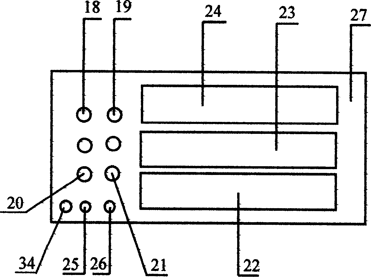
[0015] refer to image 3 , the instrument assembly 27 consists of the left front wheel water spray indicator 18, the right front wheel water spray indicator 19, the left rear wheel water spray indicator 20, the right rear wheel water spray indicator 21, the water meter 22, and the front wheel water km Meter 23, front and rear wheel water mileage meter 24, front wheel water supply pump switch 25, rear wheel water supply pump switch 26 and front and rear wheel share water supply pump switch 34 to form. The instrument assembly 27 is located on the instrument panel in the cab of the car. When each water nozzle normally sprays water, the water spray sensor turns on each corresponding water spray indicator light. When a certain water nozzle is blocked and cannot normally spray water, the corresponding The sprinkler sensor turns off its corresponding sprinkler indicator light. The liquid level sensor 15 can effectively sense the height of the water level in the water tank 1, and tra...
PUM
 Abstract
Description
Claims
Application Information