

Method for producing liquefied petroleum gas
A technology of liquefied petroleum gas and manufacturing method, applied in the petroleum industry, hydrocarbon production from carbon oxides, gas fuel, etc.
- Summary
- Abstract
- Description
- Claims
- Application Information
AI Technical Summary
Problems solved by technology
Method used
Image

Examples
Embodiment 1
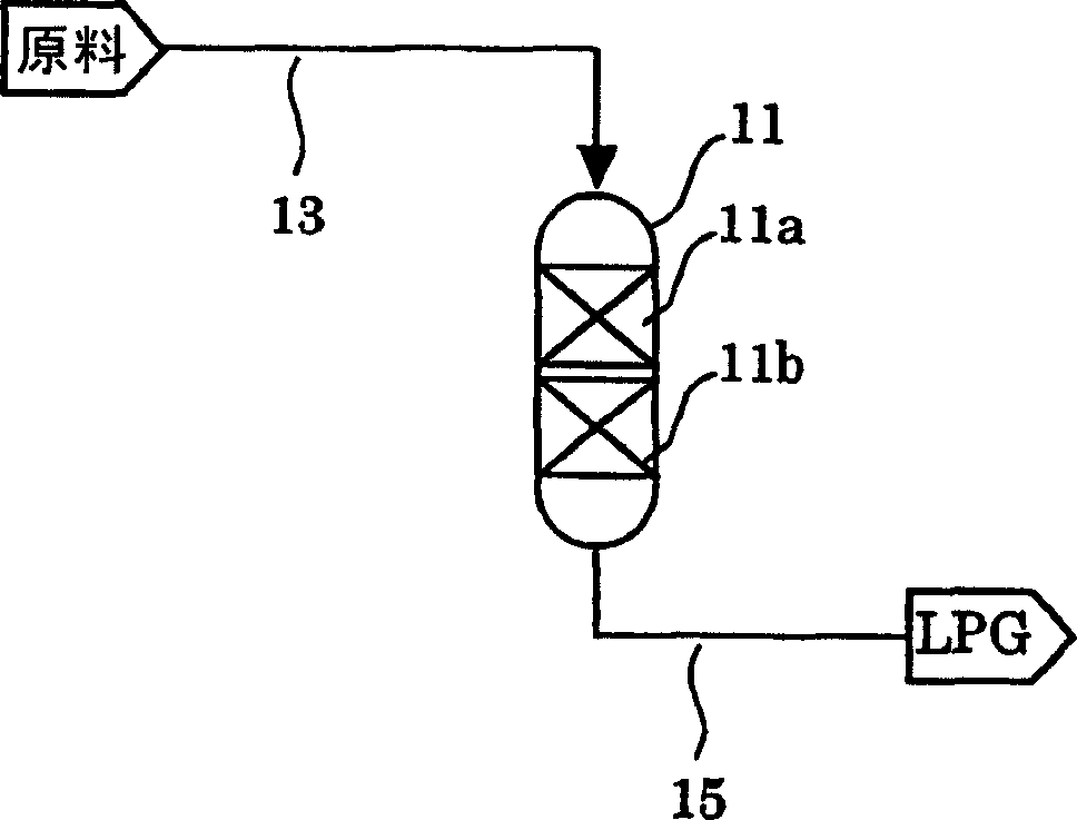
[0216] use figure 1 The LPG manufacturing apparatus shown manufactures LPG. As a catalyst for olefin-containing gas synthesis, a dry standard 73.5% by weight of H-ZSM-5 with a Si / Al ratio (atomic ratio) of 25.0, and a dry standard 26.5% by weight of alumina bonded A catalyst obtained by mixing a mixture (manufactured by Catalyst Chemicals Industry Co., Ltd., Kataroid AP), wet molding, drying and firing. As the catalyst for the hydrogenation of the olefin-containing gas, a 2.0% by weight Pt / C catalyst (manufactured by N.E. CHEMCAT Co., Ltd.) was used. Both the catalyst for the synthesis of olefin-containing gas and the catalyst for hydrogenation of olefin-containing gas used the same 1 / 32-inch cylindrical extruded product.
[0217] Make the raw material gas that is composed of methanol 50% (mol) and hydrogen 50% (mol) pass through the front stage (50% of the reactor volume) as the first catalyst layer composed of the above-mentioned olefin-containing gas synthesis catalyst, a...
Embodiment 2
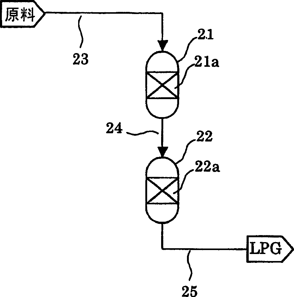
[0220] use figure 2 The LPG manufacturing apparatus shown manufactures LPG. As the catalyst for synthesizing olefin-containing gas, the same catalyst for synthesizing olefin-containing gas as in Example 1, and a catalyst in which 0.2% by weight of Pt was carried on the same catalyst for synthesizing olefin-containing gas as in Example 1 (hereinafter referred to as Catalysts for the isomerization and hydrogenation of olefin-containing gases). In addition, as the catalyst for hydrogenating olefin-containing gas, the same catalyst for hydrogenating olefin-containing gas as in Example 1 was used. In addition, the catalyst for isomerization and hydrogenation of olefin-containing gas is a catalyst for synthesis of olefin-containing gas having the function of a catalyst for hydrogenation of olefin gas.
[0221] Make the raw material gas of the same composition as in Example 1, the part that passes volume 2 / 3 from the reactor inlet is the above-mentioned olefin-containing gas synth...
Embodiment 3
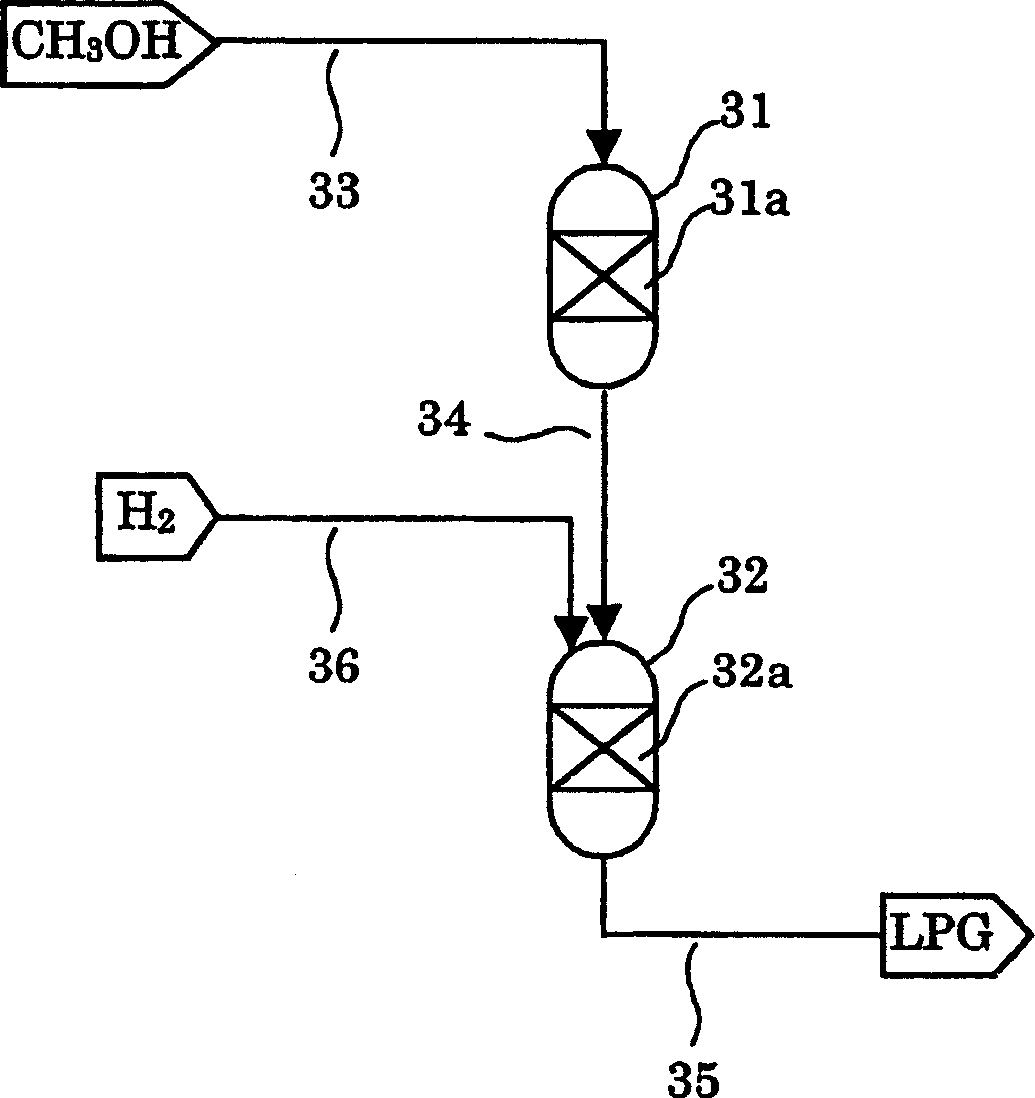
[0225] use image 3 The LPG manufacturing apparatus shown manufactures LPG. As the catalyst for synthesizing olefin-containing gas, the same catalyst for synthesizing olefin-containing gas as in Example 1 was used. As the catalyst for hydrogenation of olefin-containing gas, the same catalyst for hydrogenation of olefin-containing gas as in Example 1, and the same catalyst for isomerization and hydrogenation of olefin-containing gas as in Example 2 were used.
[0226] A raw material gas having a composition of 50% by mole of methanol and 50% by mole of water vapor was passed through the first catalyst layer composed of the above-mentioned catalyst for synthesizing olefin-containing gas. The conditions of the reaction are: reaction temperature: reactor inlet control temperature 330°C, maximum temperature of the catalyst layer 365°C; reaction pressure: methanol partial pressure 70kPa, relative to the catalyst in the first catalyst layer, the methanol liquid space-hour velocity i...
PUM
 Abstract
Description
Claims
Application Information