Vertical pump for mine

A technology for vertical pumps and mines, applied in the field of vertical pumps for mines - light-duty submersible pumps for sand removal, can solve the problems of increased pressure in the cavity of the motor chamber, easy leakage and damage to the seal of the motor shaft hole, and large pressure fluctuations. Simple structure, ideal safety effect, easy to manufacture effect

Active Publication Date: 2006-03-29
王庆武
View PDF0 Cites 73 Cited by
  • Summary
  • Abstract
  • Description
  • Claims
  • Application Information

AI Technical Summary

Problems solved by technology

Therefore, the pressure in the cavity of the motor chamber will increase during operation, and the pressure will decrease afte

Method used


Image

  • Vertical pump for mine
  • Vertical pump for mine
  • Vertical pump for mine

Examples


Embodiment Construction

[0029] The present invention will be further described below in conjunction with the accompanying drawings.

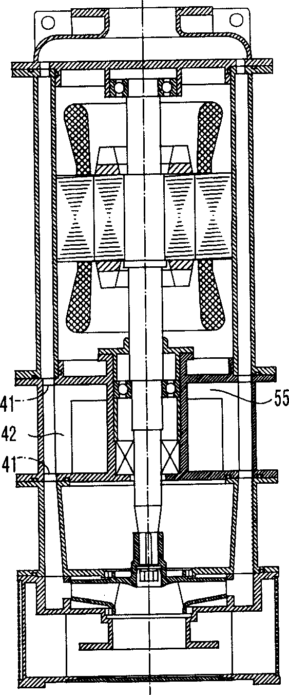
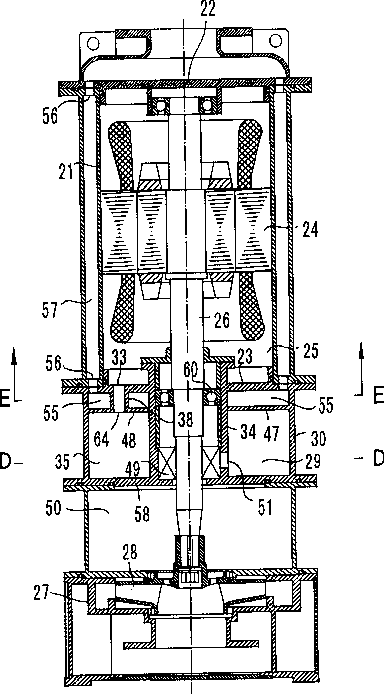
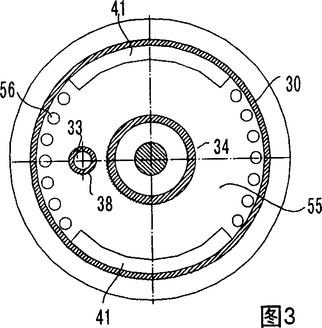
[0030] figure 1 - Fig. 4 is a set of diagrams illustrating an embodiment of the present invention. figure 2 Among them, the mine vertical pump—the light sand discharge submersible pump has a pump body 27, a pump shaft 26, an impeller 28 and a motor. Its motor has a casing 21 , an upper end cover 22 , a lower end cover 23 and a stator rotor 24 . The casing 21 together with the upper end cover 22 and the lower end cover 23 forms a closed motor chamber cavity 25 . The motor shaft hole has a mechanical seal 49. The outer oil chamber 29 outside the cylinder body 34 with the lower bearing 60 and the mechanical seal 49 inside has an oil through hole 51 communicating with the mechanical seal 49 in the cylinder body 34 body. In Fig. 4, the two sides of the two water passage chambers 42 are respectively connected with the outer oil chamber 29 and the outer space chamber 35...


PUM


Abstract

The invention is a mine vertical pump being as a light sand-discharging submersible pump in which are assembled a lower bearing, a mechanical sealed outer oil chamber outside the barrel, oil-passing hole in communication with the mechanical seal inside the barrel. The openings of the overflow pipe and the long sleeve are both disposed in the middle of the three-dimensional space in the outer cavity.

Description

technical field [0001] The present invention relates to a mine vertical pump - a light submersible sand discharge pump, which is an amphibious water pump for both land and underwater use, and is also suitable for transporting impurity submersible pumps or sand discharge submersible pumps containing solid abrasive particles in the liquid . Background technique [0002] The motor of the submersible pump needs to be highly sealed. When discharging impurities, especially sand, its motor shaft hole seal is easily damaged. In the existing old-fashioned submersible pump, once the shaft hole seal leaks inward, the grease of the lower bearing will be washed away. Once the bearing is insufficiently lubricated, it will cause a series of mechanical failures until the motor is burned. Further analysis shows that when the submersible pump discharges sand, the shaft power is unstable, and the windings and bearings are prone to heat. Therefore, the pressure in the cavity of the motor cha...

Claims


Application Information

Patent Timeline
IPC IPC(8): F04D29/06F04D13/08
Inventor 王庆武
Owner 王庆武
Why Eureka
Try Eureka