
Three phase external rotor double salient pole permanent magnet brushless electric generator

A permanent magnet brushless and generator technology, applied in the direction of synchronous machines, electrical components, electromechanical devices, etc., can solve the problems of motor output limitation, increased cost, and control system complexity, and achieve high reliability, good high-speed performance, The effect of increasing the moment of inertia

Inactive Publication Date: 2006-03-29
SOUTHEAST UNIV
View PDF0 Cites 9 Cited by
  • Summary
  • Abstract
  • Description
  • Claims
  • Application Information

AI Technical Summary

Problems solved by technology

However, the switched reluctance motor mainly works by the reluctance torque, and the output of the motor is limited to a certain extent. Moreover, the power output circuit of the switched reluctance generator must use controllable power devices, which increases the cost and the complexity of the control system. At present, switched reluctance motors are mainly used in some special occasions such as starter generators for aircraft

Method used


Image

  • Three phase external rotor double salient pole permanent magnet brushless electric generator
  • Three phase external rotor double salient pole permanent magnet brushless electric generator
  • Three phase external rotor double salient pole permanent magnet brushless electric generator

Examples


Embodiment Construction

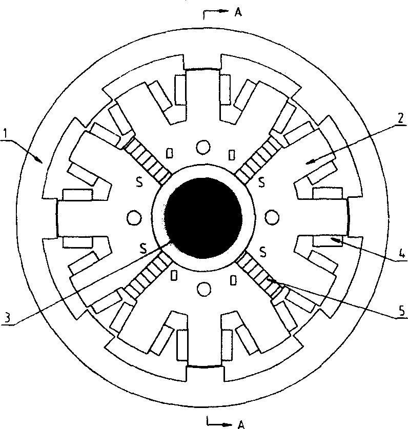
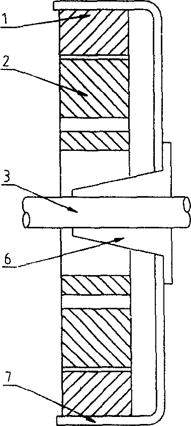
[0019] The generator has a structure in which the stator is inside and the rotor is outside. The permanent magnets and armature windings are located on the stator side. The stator is fixed through four mounting holes. The rotor has no windings, no brushes, and no permanent magnets. The rotor passes through the casing and The shaft sleeve seat is connected with the rotating shaft. On the yoke of the stator, there are 4 (two or more) NdFeB rare earth permanent magnets evenly distributed on the yoke of the stator. The polarities of the 4 permanent magnets 5 are according to N, S, S, N, N, S, S, N forms are distributed, and the excitation magnetic field of the generator is provided by the rare earth permanent magnet. The stator is evenly distributed with 12 salient poles, and the outer rotor is evenly distributed with 8 salient poles. The stator and rotor are all silicon steel sheet laminated structures. The number of salient poles of the rotor is less than the number of salient ...


PUM


Abstract

A three-phase double convex pole permanent magnet brushless generator is in the structure of a stator inside and a rotor outside, the magnet and an armature winding are set on the stator fixed on the base by four installing holes, the rotor is connected with the shaft by the shell and a shaft sleeve base, four magnets are distributed uniformly along the circum at the yoke of the stator, the poles of which are distributed in N,S,S,N,N,S,S,N, 12 convex poles are uniformly distributed on the outer circum of the stator, 8 convex poles are uniformly distributed on the inner circum of the rotor and placed on the two face to face poles of the stator and two face to face vertical poles connected with them and the centralized windings of the four poles are serial to one three-phase armature winding in 120deg. difference.

Description

technical field [0001] The invention relates to a structural design technology of a novel permanent magnet generator, and belongs to the technical field of motor design. Background technique [0002] In recent years, power generation systems that can realize variable speed and constant frequency have been paid more and more attention to and applied, such as independent or grid-connected wind power generation systems, mobile independent power generation systems, etc. The driving force can be wind power, diesel engines or gasoline engines. There are three main types of generators in high-frequency power generation systems, namely doubly-fed asynchronous motors, permanent magnet synchronous motors and switched reluctance motors. Doubly-fed asynchronous motors are low in cost, but complex in structure, poor in reliability, and large in size. Currently, they are mainly used in large-capacity grid-connected generator sets. The permanent magnet synchronous motor replaces the rotor...

Claims


Application Information

Patent Timeline
Patent Type & Authority Applications(China)
IPC IPC(8): H02K21/38
Inventor 程明张建忠
Owner SOUTHEAST UNIV
Learn More