
Axial housing type gear pump mounted with rolling bearing and gear motor

A technology of rolling bearing and gear motor, which is applied to rotary piston/swing piston pump components, rotary piston pumps, components of pumping devices for elastic fluid, etc. Sealing, increased displacement, etc., to prevent abnormal noise, large impact load, and prevent deformation

Inactive Publication Date: 2006-04-05
程安强
View PDF0 Cites 12 Cited by
  • Summary
  • Abstract
  • Description
  • Claims
  • Application Information

AI Technical Summary

Problems solved by technology

However, this bushing gear pump also has certain limitations, which are reflected in two aspects: one is that only sliding bearings can be used but not rolling bearings; the other is that the displacement of the bushing gear pump with sliding bearings can only be 150cm 3 Below / rev, large displacement is difficult to achieve
The reason: because the axial sealing oil of the high-pressure oil is set on the outside of the shaft sleeve, the high-pressure oil enters the outer circumference of the shaft sleeve outside the side plate, so that the shaft sleeve is under the action of high-pressure oil, and because the shaft sleeve The received axial force and radial force interfere with each other, and it is difficult to maintain a good axial seal. In addition to bearing the inherent radial force transmitted to the shaft sleeve through the gear shaft and bearing, the shaft sleeve must also It bears the hydraulic pressure directly acting on the outer circumference of the bushing from high-pressure oil, which will cause the deformation of the bushing, thereby causing the deformation of the bearing installed in the bushing, making the bearing unable to work normally and producing abnormal noise, thereby limiting the increase in displacement.
As a result of the above, the bushing gear pump cannot use rolling bearings with small clearance and the displacement cannot exceed 150cm 3 / rev

Method used


Image

  • Axial housing type gear pump mounted with rolling bearing and gear motor
  • Axial housing type gear pump mounted with rolling bearing and gear motor
  • Axial housing type gear pump mounted with rolling bearing and gear motor

Examples


Embodiment Construction

[0027] In order to further understand the invention content, characteristics and effects of the present invention, the following examples are given, and detailed descriptions are as follows in conjunction with the accompanying drawings:

[0028] The structure of the present invention is suitable for both gear pumps and gear motors, and will be described separately below as gear pumps or gear motors.

[0029] As the gear pump is detailed below:

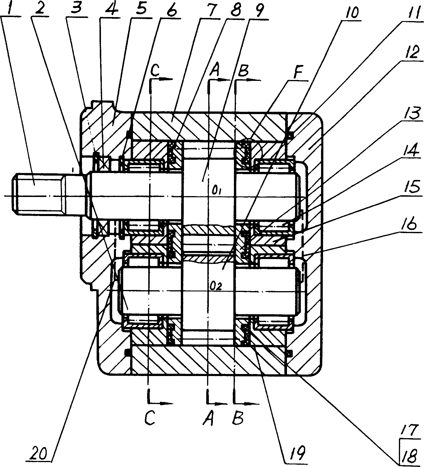
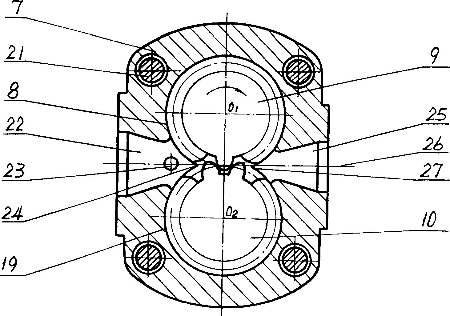
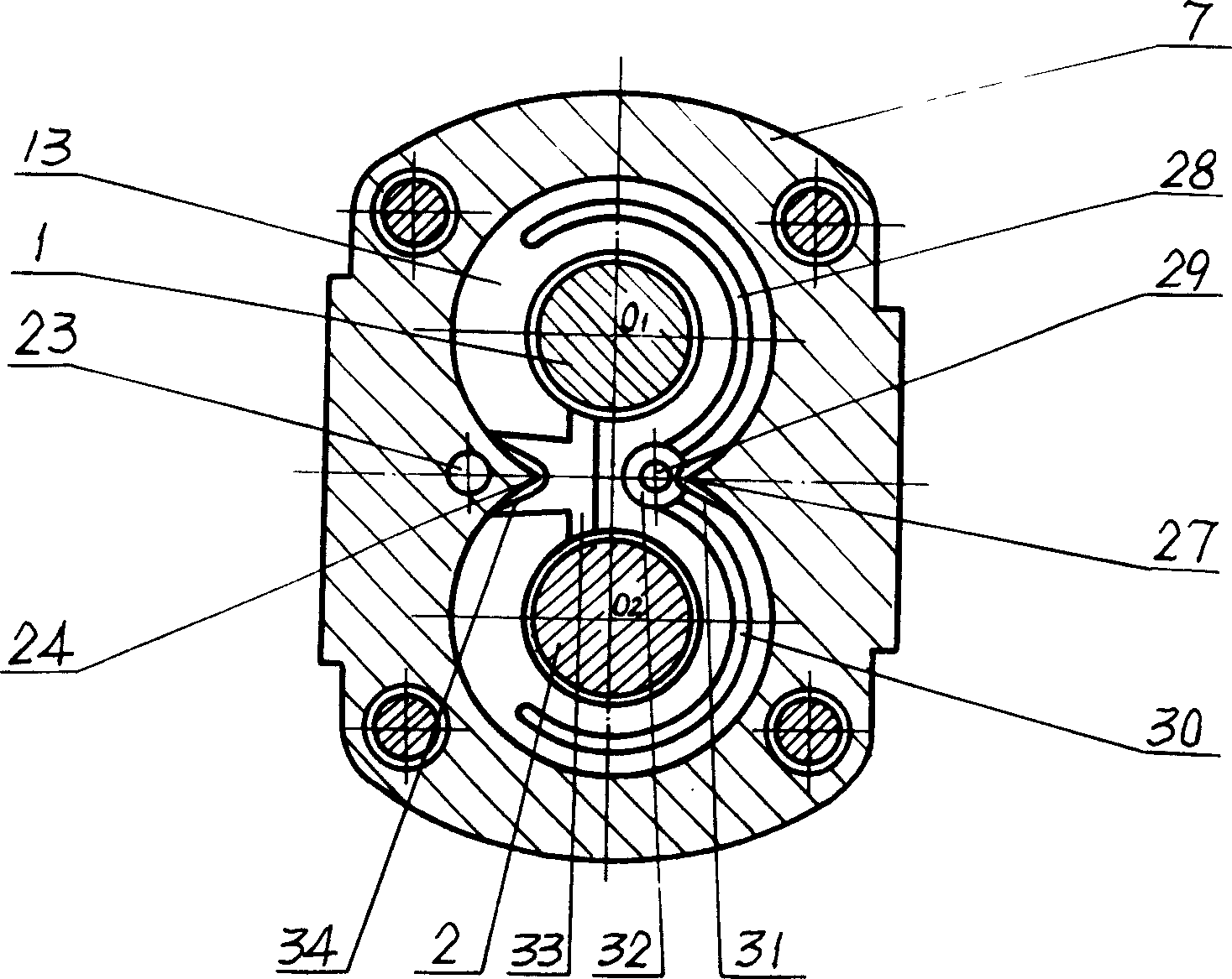
[0030] see Figure 1 to Figure 8 . There are a front cover 5, a housing 7 with an oil inlet and an oil outlet, and a rear cover 12, and they are fastened together with bolts 21, and grooves are respectively opened on the joint surfaces of the front cover and the rear cover with the housing And be equipped with sealing rubber ring 11 in order to prevent oil leakage. On the shell, there are two equal diameters perpendicular to the front cover and the rear cover and at its center O 1 and O 2The "8"-shaped gear holes 8 and 19 intersec...


PUM


Abstract

The invention discloses a bearing gear pump and gear motor with rolling bearing, which is characterized by the following: fixing a couple of gear pairs with lateral plate on each side in the '8' keyhole-shaped case inner wall; setting four axle sleeves with bearing on the outer side of lateral plate; setting high pressure oil axial sealing oil system; the appearance of two interapplying axle sleeves is the same as cave keyhole-shaped, which is inserted in the zero air void matching cave with rolling bearing in the axle sleeve. The axle sleeve doesn't bear liquid pressure action any longer because of zero air void matching between axle sleeve and cave, which avoids the deformation and noise of axle sleeve and provides large displacement gear pump and gear motor for engineering machinery and mining machinery under terrible working condition.

Description

technical field [0001] The invention belongs to a fluid transmission device, in particular to a shaft sleeve type gear pump and a gear motor which are used as a power source or an actuator in a hydraulic system and are equipped with rolling bearings. Background technique [0002] A gear pump in which a pair of meshing gears with shafts at both ends and a bushing with bearings are all installed in the housing is called a bushing gear pump. With slight changes on this basis, it can be developed into a bushing gear motor. [0003] At present, the bearing used in this bushing gear pump is a sliding bearing. Since it came out decades ago, it can better maintain the concentricity between the front bearing and the rear bearing in structure, and the structure is simple and reasonable. It has become the preferred structure of gear pumps and has been widely used. However, this bushing gear pump also has certain limitations, which are reflected in two aspects: one is that only slidin...

Claims


Application Information

Patent Timeline
IPC IPC(8): F04C2/18F04C29/06
Inventor 程安强
Owner 程安强
Learn More