
Compressor

一种压缩机、制冷剂的技术,应用在压缩机领域,能够解决焊接部耐压强度下降、容器主体应变增大、壁厚大等问题,达到电流密度的变动小、耐压强度提高、稳定焊接的效果

Inactive Publication Date: 2006-04-05
SANYO ELECTRIC CO LTD
View PDF0 Cites 4 Cited by
  • Summary
  • Abstract
  • Description
  • Claims
  • Application Information

AI Technical Summary

Problems solved by technology

For this reason, the diameter of the projection welded portion also increases, and there is a problem that the compressive strength of the welded portion decreases.
In addition, since the tube fixing method is simply to insert a copper tube into the sleeve body and braze it, it is difficult to attach the tube to the sleeve body at right angles, and the installation of the refrigerant introduction tube, etc. and so on
[0009] Additionally, when having Figure 7 In the compressor with the sleeve of the shown shape, since the wall thickness of the sleeve on the side of the projection welding is relatively large, when the sleeve is installed on the container body by welding, the container body is pushed by a large seat, and there is a The problem of increased strain in the body

Method used


Image

  • Compressor
  • Compressor
  • Compressor

Examples


Embodiment 1

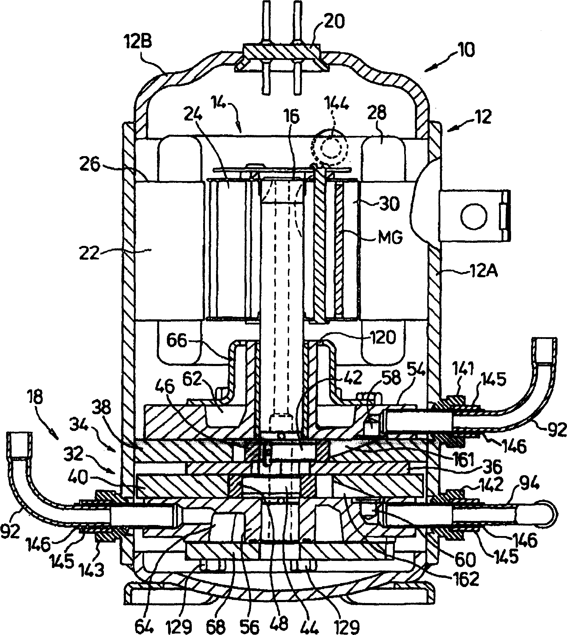
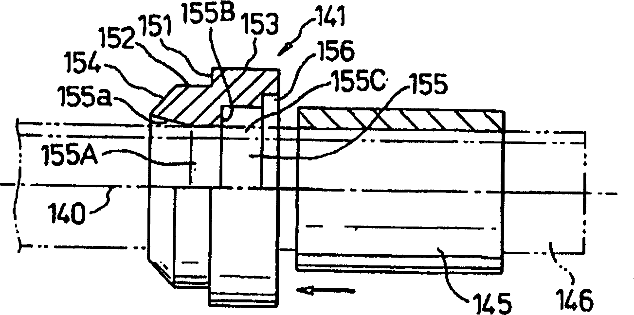
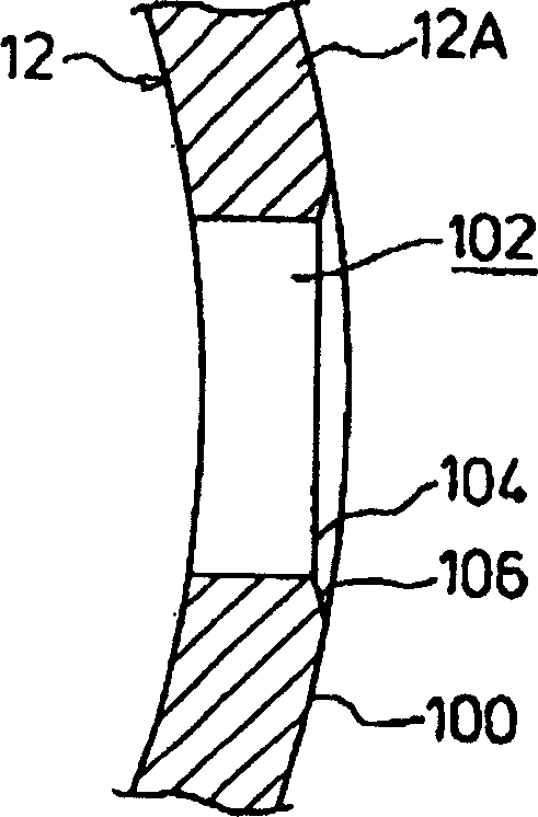
[0028] Below, according to Figure 1 ~ Figure 4 An embodiment of the present invention will be described in detail.

[0029] figure 1 As an example of the compressor of the present invention, a vertical cross-sectional view of an internal high-pressure multi-stage (two-stage) compression rotary compressor 10 having first and second rotary compression units 32 and 34 is shown. For easy understanding, in Figure 1 ~ Figure 4 , for having the same as in the above Figure 6 , Figure 7 The same symbols are used for the same functions as those explained.

[0030] exist figure 1 Among them, symbol 10 is the carbon dioxide (CO 2 ) is an internal high-pressure type multi-stage (two-stage) compression rotary compressor that performs compression. The rotary compressor 10 is composed of a cylindrical airtight container 12, a drive unit 14, and a rotary compression mechanism part 18. The airtight container 12 is composed of Made of steel plate, the driving unit 14 is accommodated ...


PUM


Abstract

The invention provides a compressor which has a sleeve (141), and the sleeve (141) is arranged correspondingly to a through hole (102) of a bending surface (100) which forms a sealed container (12), and is connected with a refrigerant pipe. The sleeve (141) has a small outer diameter part (152), a big outer diameter part (153) and a diameter shrinking part (154) which are arranged in a continuous way through an annular step part (151), the diameter shrinking part (154) takes a capitellate shape at the opening end side of the small outer diameter part (152), a communicating pore (155) which runs through the small outer diameter part (152)and the big outer diameter part (153) has a small inner diameter part (155A) and a big inner diameter part (155C), the small inner diameter part (155A) is mainly arranged at the small outer diameter part (152), the big inner diameter part (155C) is connected with the small inner diameter part (155A) through an annular step part (155B), and is arranged at the big outer diameter part (153), a diameter expanding part (155a), the inner diameter of which gradually increases towards the opening end side, is arranged at the opening end side of the small inner diameter part (155A), and a tube component (145) made of copper is embedded into the big outer diameter part (155C) to be carried out with solder brazing under the state that one end is contacted with the step part (155B), so as to be fixed in the sleeve (141); thus, the compressor which can enable the sleeve arranged in the sealed container through projection welding to be miniature is provided, and the refrigerant pipe and the sleeve are simply connected with a right angle, thereby the sealed container cannot suffer the seat thrust greatly when the sleeve is arranged in the sealed container by welding.

Description

technical field [0001] The present invention relates to a compressor for compressing refrigerant in refrigeration equipment such as air conditioners, water heaters, car air conditioners, product showcases, freezers / refrigerators, and automatic vending machines. Background technique [0002] In such a compressor, such as an internal intermediate pressure type multi-stage compression rotary compressor, the refrigerant gas is sucked from the refrigerant inlet pipe through the suction hole of the first rotary compression unit to the low-pressure chamber side of the cylinder, and is drawn by the roller and the vane. Compressed by the action, it becomes an intermediate pressure, and is discharged from the high-pressure chamber side of the cylinder into the airtight container through the discharge hole and the discharge muffler chamber. [0003] Then, the intermediate-pressure refrigerant gas in the airtight container is sucked into the low-pressure chamber side of the cylinder fro...

Claims


Application Information

Patent Timeline
Patent Type & Authority Applications(China)
IPC IPC(8): F04C29/12
CPCF04C18/3564F04C23/001F04C23/008F04C2240/30F04C2230/231F01C21/10F04C2240/806F05B2210/12F05B2230/232F05B2240/14Y10S417/902
Inventor 里和哉
Owner SANYO ELECTRIC CO LTD
Learn More