Method for producing permeability type die steel
A manufacturing method and ventilation technology, applied in the field of mold manufacturing, can solve the problems of inability to effectively control the size, position and continuity of ventilation holes, inability to ensure 100%, and inability to achieve air permeability, etc., to increase processing time, improve quality, The effect of balancing the internal and external pressure difference
- Summary
- Abstract
- Description
- Claims
- Application Information
AI Technical Summary
Problems solved by technology
Method used
Image


Examples
Embodiment 1
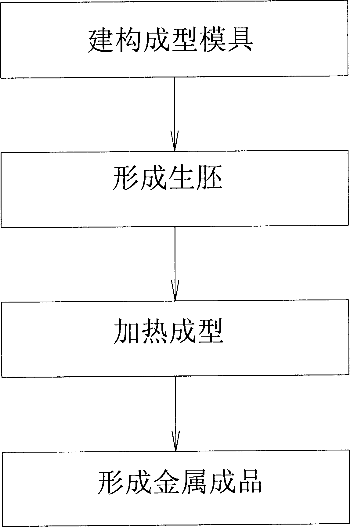
[0041] Embodiment 1: as figure 1 Shown, the manufacture method step of air-permeable mold steel of the present invention is as follows:
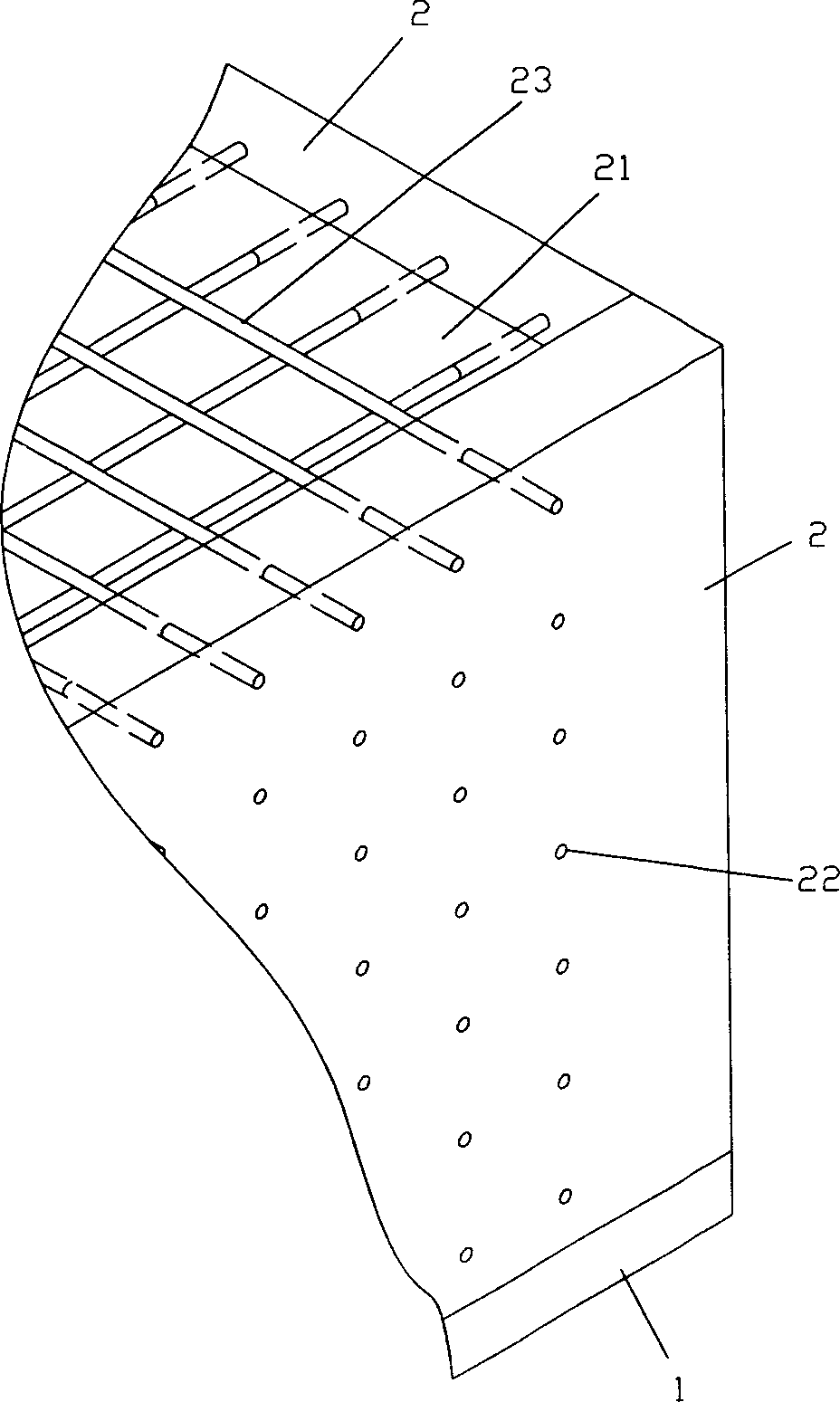
[0042] (1) Constructing the forming mold: see figure 2 As shown, at the periphery of the flat plate 1, four fixed blocks 2 are stacked and fixed to form a forming mold with an accommodating space 21. The four fixed blocks 2 are arranged relatively equidistantly with a number of tiny Through hole 22 (see image 3 ), and each through hole 22 on the opposite fixing block 2 is connected with a polymer wire 23, through which the criss-crossing polymer wires 23 can be densely distributed in the accommodation space 21 surrounded by the fixing block 2. The shape of the fixed block 2 of this molding die can be set according to the desired shape of the mould.
[0043] (2) Embryo formation: see Figure 4 As shown, after kneading the metal powder and the binder, put it into the accommodation space 21 surrounded by the fixed block 2, and after it is...
Embodiment 2
[0047] Embodiment 2: as Figure 8 and Figure 9 Shown, the manufacture method step of air-permeable mold steel of the present invention is as follows:
[0048] (1) Constructing the forming mold: On the flat plate 1, use one or more frame-shaped fixed blocks 2 to stack up and down to fix, and in each fixed block 2, insert a mesh-shaped polymer wire 23: After one or more fixed blocks 2 are stacked, they encircle a forming mold with an accommodating space 21 , and the mesh-shaped polymer wires 23 are stacked in the accommodating space 21 at appropriate intervals.
[0049] Step (2), step (3) and step (4) are basically consistent with those in Embodiment 1, until a finished metal product 32 with vent holes is completed (see Figure 7 ), which will not be repeated here.
Embodiment 3
[0050] Embodiment 3: as Figure 10 and Figure 11 Shown, the manufacture method step of air-permeable mold steel of the present invention is as follows:
[0051] (1) Constructing the forming mold: First, a number of polymer wires 23 are vertically penetrated and fixed on the bottom plate 8, and then one or more frame-shaped fixing blocks 2 are used to stack and fix, and each fixed block 2 , a mesh-like polymer wire 23 is inserted. After one or more fixed blocks 2 are stacked, they encircle a forming mold with an accommodating space 21, and the vertical polymer wires 23 and the mesh-like polymer wires 23 are located in the accommodating space at appropriate distances from each other. Within 21. After mixing the metal powder and the binder, put it into the above-mentioned accommodating space 21, and then cover the cover plate 6 on the top, the cover plate 6 is provided with a cover plate through-hole 7 relative to the polymer wire 23 for the polymer wire 23 through fixed.
...
PUM
 Abstract
Description
Claims
Application Information
 - R&D Engineer
- R&D Manager
- IP Professional
- Industry Leading Data Capabilities
- Powerful AI technology
- Patent DNA Extraction
Browse by: Latest US Patents, China's latest patents, Technical Efficacy Thesaurus, Application Domain, Technology Topic.
© 2024 PatSnap. All rights reserved.Legal|Privacy policy|Modern Slavery Act Transparency Statement|Sitemap