Light emitting device package and back light unit for liquid crystal display using the same

A technology for backlight units and components, applied to semiconductor devices of light-emitting elements, electroluminescent light sources, semiconductor devices, etc., can solve problems such as temperature rise

Inactive Publication Date: 2006-04-19
LG ELECTRONICS INC
View PDF0 Cites 17 Cited by
  • Summary
  • Abstract
  • Description
  • Claims
  • Application Information

AI Technical Summary

Problems solved by technology

However, the problem with the brightness required by large display devices is that the heat generated is four times that of the existing technology, causing such a problem that if the ambient temperature is 30 degrees Celsius, the temperature of the back sheet rises to almost 70 degrees Celsius

Method used


Image

  • Light emitting device package and back light unit for liquid crystal display using the same
  • Light emitting device package and back light unit for liquid crystal display using the same
  • Light emitting device package and back light unit for liquid crystal display using the same

Examples


Embodiment Construction

[0028] Preferred embodiments of the present invention will now be described in detail with reference to the accompanying drawings.

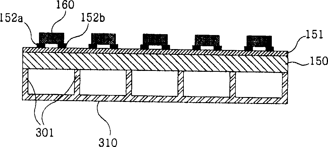
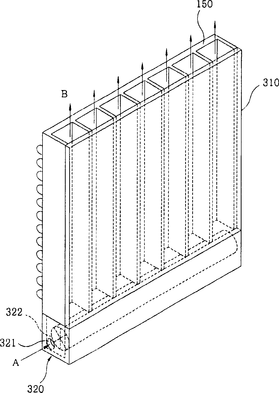
[0029] figure 2 is a schematic perspective view of an LED assembly according to the present invention.

[0030] The LED assembly includes: a metal substrate (150), an insulating sheet (151) formed on the upper surface of the metal substrate (150), and a plurality of electrode wires (152a, 152b) formed on the insulating sheet (151); LEDs (160) arranged in rows and columns to the upper surface of a plurality of electrode lines (152a, 152b); a plurality of strip-shaped protrusions (301) fixed to the lower surface of the metal substrate on one surface thereof, each a predetermined distance apart; and a guide member (310) fixed to the other surface of the protrusion (301).

[0031] refer to image 3 , a fan (322) that absorbs air through the suction port (321) is installed in the LED assembly, and a fan housing (320) is further installed, and a fa...


PUM


Abstract

A light emitting device package and a back light unit for liquid crystal display using the same wherein a fan is used to forcibly cool an LED package and a back light unit for LCD to increase the heat radiation efficiency and to prevent the degradation of the device.

Description

technical field [0001] The present invention relates to a light emitting device assembly and a backlight unit of a liquid crystal display using the assembly. Background technique [0002] In general, a light emitting diode (LED) is a device that converts electricity into light by the principle that if a current is made to flow in a forward direction into a junction including two different semiconductors, electrons and holes recombine at the junction region to generate light beams. Said LEDs have the advantage that they are shock-resistant and, under certain conditions, have an almost eternal lifetime. [0003] LEDs have been developed beyond incandescent lamps. Also, efforts have recently been made to use high-efficiency LEDs as light emitting devices. However, said LEDs are not as efficient as fluorescent lamps and do not seem likely to exceed the efficiency of fluorescent lamps for a short period of time. [0004] Although the efficiency of LEDs cannot be compared with ...

Claims


Application Information

Patent Timeline
Patent Type & Authority Applications(China)
IPC IPC(8): G02F1/1335H05B33/00F21V29/02H01L33/44H01L33/62H01L33/64
CPCG02F2001/133628G02F1/133603F21V29/02F21Y2101/02F21V29/74F21Y2115/10G02F1/133628G02F1/1335F21V29/67F21V29/763
Inventor 李昇敏张峻豪李泰熹
Owner LG ELECTRONICS INC
Why Eureka
Try Eureka