
Boring device for borehole wall

A drilling device and well wall technology, applied in drilling equipment and methods, drilling equipment, earthwork drilling, etc., can solve the problems affecting oil well life, limited perforation depth, high cost, and achieve broad field application prospects, drilling The effect of fast hole speed and large hole depth

Inactive Publication Date: 2006-04-26
SHENGLI PETROLEUM ADMINISTRATION BUREAU DRILLING TECH ACAD SINOPEC
View PDF0 Cites 2 Cited by
  • Summary
  • Abstract
  • Description
  • Claims
  • Application Information

AI Technical Summary

Problems solved by technology

At present, concentrated energy perforation technology is generally used to solve this problem. This technology has been around for quite a long time. It is easy to implement and easy to operate and maintain. Inherent defects such as impact damage, affecting the life of the oil well, and greatly reducing the permeability of the rock around the hole wall
In order to overcome the deficiencies of concentrated energy perforation technology, domestic and foreign engineers and technicians have carried out a lot of research, and also formed "water jet deep penetration perforation", "sandblasting perforation", "bullet perforation" and "laser perforation". However, the developed technology has poor working stability (such as water jet deep penetration perforation), high cost (such as laser perforation), and limited scope of application (such as bullet perforation and sandblasting perforation). ) and other deficiencies, it has not really replaced shaped energy perforation and has become a widely used technology

Method used


Image

  • Boring device for borehole wall
  • Boring device for borehole wall

Examples


Embodiment Construction

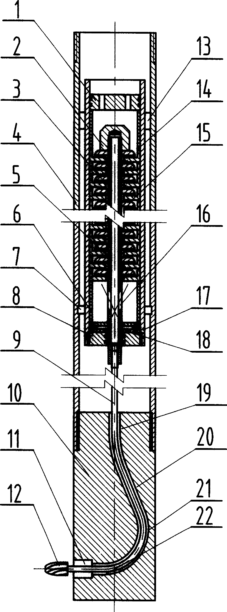
[0009] The present invention will be further described now in conjunction with the accompanying drawings of the description.

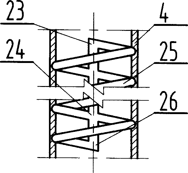
[0010] When the present invention is used for borehole drilling, the upper and lower ends of the outer cylinder [4] are respectively connected to the pipe string and the diverter [10], and the inner wall of the middle section of the outer cylinder [4] is processed with a down slideway [24] And up slideway [25], downlink slideway [24] becomes straight line, uplink slideway [25] becomes spiral shape, downlink slideway [24] and uplink slideway [25] end-to-end smooth connection, stator [15] matches Put it into the inner cylinder [17], set the rotor [3] on the hollow shaft [5], install the stator [15] and the rotor [3] at intervals, and fix the rotor [3] axially with the compression nut [2] , the upper end and the lower end of the inner cylinder [17] are respectively loaded into the upper limit sleeve [14] and the lower limit sleeve [6], and the upper end o...


PUM


Abstract

The invention provides a borehole wall drilling device, which comprises the following parts: inner cylinder, outer cylinder, flexible shaft, stator, rotor, drill, steering unit and so on. The working elementary is characterized by the following: activating the rotor through hydraulic energy; anchoring the hollow flexible shaft with drill; piercing the annular tube and cement ring along forward direction of the shaft; drilling ground to form a pretty deep hole through the underground pollution band. The device drilling speed is rapid and operation is reliable without impacting annular tubes, cement ring and ground.

Description

technical field [0001] The invention belongs to the auxiliary equipment for oil and gas drilling, well completion and oil recovery. technical background [0002] In order to keep the wellbore stable and isolate different formation pressure systems, the commonly used method is to run a casing in the wellbore, and then inject cement into the annular space between the casing and the formation for sealing. This brings about a problem, how to establish a channel to communicate the wellbore and the formation, so as to realize the extraction or injection of fluids such as oil and gas. At present, concentrated energy perforation technology is generally used to solve this problem. This technology has been around for quite a long time. It is easy to implement and easy to operate and maintain. Inherent defects such as impact damage, affecting the life of the oil well, and greatly reducing the permeability of the rock around the hole wall. In order to overcome t...

Claims


Application Information

Patent Timeline
Patent Type & Authority Applications(China)
IPC IPC(8): E21B43/00E21B7/00
CPCE21B7/061
Inventor 倪红坚韩来聚李作会王敏生
Owner SHENGLI PETROLEUM ADMINISTRATION BUREAU DRILLING TECH ACAD SINOPEC
Learn More