

Welding joint of fuel tank
A technology of welding joints and fusion welding, which is applied in the direction of non-detachable pipe connections, pipes/pipe joints/fittings, passing components, etc., can solve the problems of fuel penetration resistance and strength reduction, and achieve good fuel penetration resistance, excellent Effect of fuel exudation resistance and weld strength
Inactive Publication Date: 2006-04-26
SUMITOMO RIKO CO LTD
View PDF2 Cites 10 Cited by
- Summary
- Abstract
- Description
- Claims
- Application Information
AI Technical Summary
Problems solved by technology
Method used
View moreImage
Smart ImageViewing Examples

Examples
Embodiment Construction
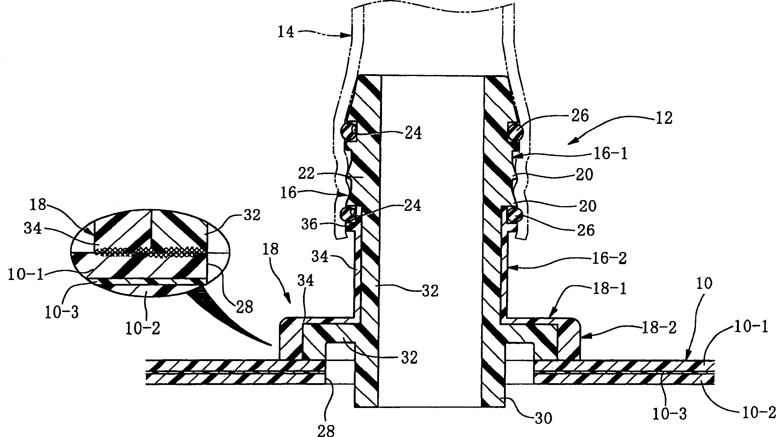
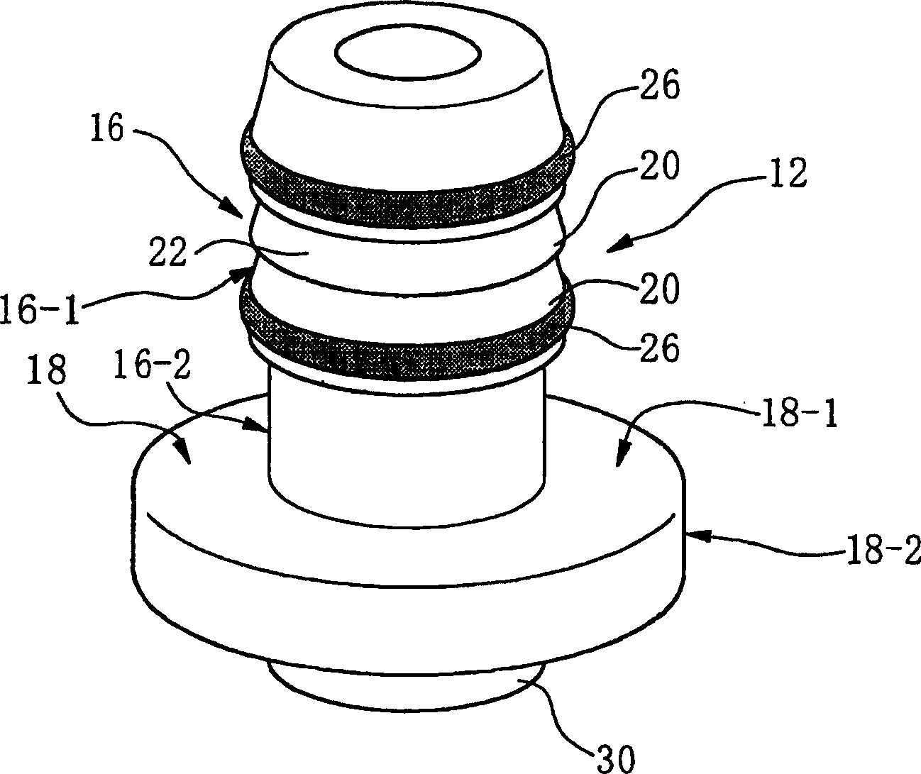
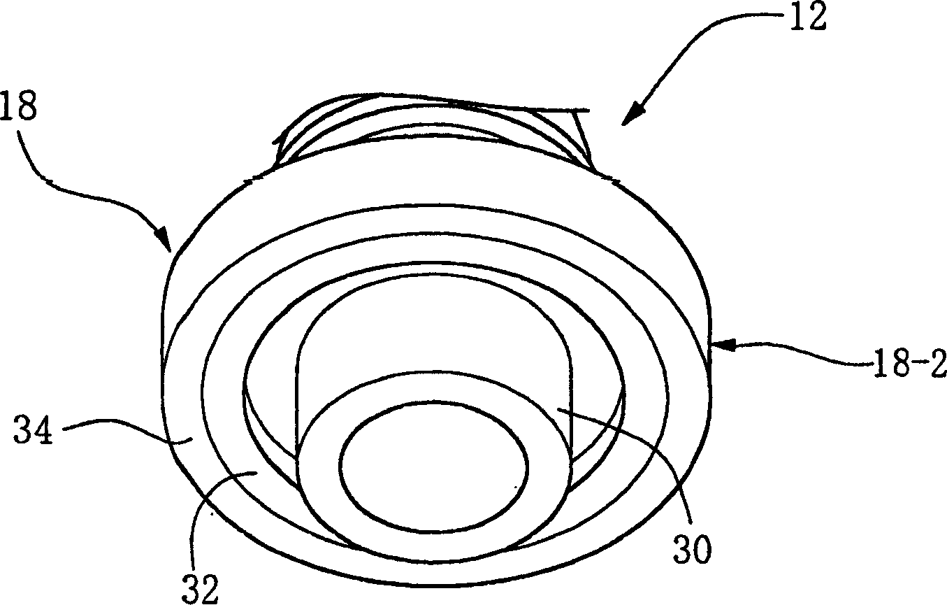
[0056] Now, embodiments of the present invention will be described in detail with reference to the accompanying drawings.
[0057] refer to figure 1 , Reference numeral 10 denotes a resin fuel tank. Here, the fuel tank 10 includes an outer layer 10-1 and an inner layer 10-2 made by using HDPE resin, and it has a cross-sectional structure in which a thin barrier layer 10-3 is sandwiched between the outer layer and the inner layer.
[0058] In this case, the barrier layer 10-3 also forms an inner layer with respect to the outer layer 10-1.
Login to View More PUM
 Abstract
A fusion joint has a cylindrical portion as a connecting portion and an annular welded portion arranged at a base end portion of the cylindrical portion, the welded portion configured to be thermally welded to a resin-made fuel tank. The cylindrical portion is constituted by using a resin alloy material in which modified high-density polyethylene obtained by introducing a functional group with a high affinity for the hydroxyl group of an ethylene-vinyl alcohol copolymer and ethylene-vinyl alcohol The copolymer is alloyed, and at least the welded portion includes an inner layer using the resin alloy material and an outer layer using at least one of high-density polyethylene and modified high-density polyethylene and covering the inner layer on the outside.
Description
technical field [0001] The present invention relates to a resin-made joint for connecting a piping pipe or a connector to a resin-made fuel tank, and more particularly, to a resin-made welded joint that is welded to the fuel tank to constitute a connecting portion. Background technique [0002] A fuel tank mounted on an automobile is integrally provided with a joint for connecting a pipe, a connector for introducing fuel injected from an inlet into the fuel tank, and the like. [0003] Here, for example, in the case of a pipe for introducing fuel from an injection port into a fuel tank, a rubber pipe (rubber hose) has hitherto been used. However, in recent years, the permeation of fuel to the outside through the hose has been strictly controlled in consideration of environmental protection. Therefore, rubber / resin composite pipes in which the rubber hose further includes a resin barrier layer, a rubber pipe made of fluororubber having fuel permeation resistance, or a resin ...
Claims
Login to View More Application Information
Patent Timeline
 Patent Type & AuthorityApplications(China)
IPC IPC(8): F16L13/00B29C70/84B60K15/03
Inventor西山高广笹井建典片山和孝伊藤弘昭仁木伸明铃木淳一朗
OwnerSUMITOMO RIKO CO LTD