Suction filter, turbo compressor, and method of packaging the compressor

A turbo compressor and filter technology, applied in chemical instruments and methods, separation methods, dispersed particle filtration, etc., can solve problems such as increased pressure loss, no introduction of three built-in coolers, performance degradation, etc., and achieves easy assembly. Effect

Inactive Publication Date: 2006-04-26
IHI CORP
View PDF4 Cites 0 Cited by
  • Summary
  • Abstract
  • Description
  • Claims
  • Application Information

AI Technical Summary

Problems solved by technology

[0018] Therefore, there are problems such as an increase in the number of parts, and an increase in the installation area due to the separate type, resulting in an increase in size. In addition, the air piping connecting the third-stage compressor and the aftercooler

Method used


Image

  • Suction filter, turbo compressor, and method of packaging the compressor
  • Suction filter, turbo compressor, and method of packaging the compressor
  • Suction filter, turbo compressor, and method of packaging the compressor

Examples


Embodiment Construction

[0045] Hereinafter, embodiments of the suction filter of the present invention will be described with reference to the drawings.

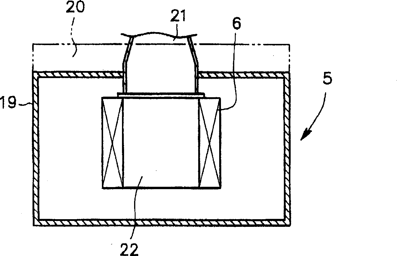
[0046] Figure 4 and Figure 5 It is a diagram showing an embodiment of the suction filter of the present invention. In the central part of the casing 19 having the suction part 20 and the discharge part 21, a chamber 23 with a closed structure having a predetermined thickness and height is provided, and the chamber An opening 24 communicating with the discharge portion 21 is provided on one side in the front-rear direction of the chamber 23 , and four openings 25 are provided on both left and right side surfaces in the thickness direction of the chamber 23 . On the outer surface of each opening 25, a small-diameter filter element mounting part 26 that is cylindrical and has an opening in the circumferential direction is installed in a horizontal state in the left-right direction. The filter element 27 of the small diameter of cylindrical shape c...


PUM


Abstract

It is designed to provide a sealed chamber in the inner central part of the housing, and filter elements are installed on both sides of the chamber, and the air flowing into the housing from the suction part is guided to the above chamber through the filter elements. Each filter element is removably embedded and mounted on the filter element mounting part having an opening. When replacing the filter elements, open the window and replace them one by one. On the cast body, the whole casting shell with the compression part of the compressor and the compressed air channel is integrally made, and the storage part for the built-in first intercooler, the second intercooler and the aftercooler is formed on it. The first intercooler, the second intercooler, and the aftercooler are accommodated in the order of arrangement described above. The outlet of the first intercooler and the suction side of the second-stage compressor, and the outlet of the second intercooler and the suction side of the third-stage compressor are respectively connected by detachable suction pipes. Also, the exhaust muffler is arranged between the monolithic casing and the oil tank.

Description

technical field [0001] The invention relates to a suction filter arranged on the suction side of the suction line of a compressor. Furthermore, the present invention relates to a turbo compressor, in particular, a turbo compressor in which compactness is desired by integrating a compression section constituting a main body of the compressor and an air cooler or a muffler, and an assembly method of the turbo compressor. Background technique [0002] First, the background art of the suction filter will be described. [0003] Among the turbo compressors, the 2-stage turbo compressor has been proposed figure 1 The structure shown in the outline of an example. That is, a suction line 4 having a suction valve 3 in the middle is connected to the suction port 2 of the first-stage compressor 1, and a suction filter 5 is mounted on one end side of the suction side constituting the suction line 4. The suction filter 5 It has a filter element 6 for removing foreign matter such as dus...

Claims


Application Information

Patent Timeline
IPC IPC(8): B01D46/24F04D29/70B01D46/42F04D29/58
Inventor 武富敏礼长谷川和三佐佐木善孝小河良行
Owner IHI CORP
Why Eureka
Try Eureka